Contents
Scenario: High Availability using VRRP (L3HA) with Open vSwitch
This scenario describes a high-availability implementation of the OpenStack Networking service using the ML2 plug-in and Open vSwitch (OVS).
This high-availability implementation augments the Scenario: Legacy with Open vSwitch architecture with Virtual Router Redundancy Protocol (VRRP) using keepalived to provide quick failover of layer-3 services. See Packet flow for VRRP operation. Similar to the legacy scenario, all network traffic on a project network that requires routing actively traverses only one network node regardless of the quantity of network nodes providing HA for the router. Therefore, this high-availability implementation primarily addresses failure situations instead of bandwidth constraints that limit performance. However, it supports random distribution of routers on different network nodes to reduce the chances of bandwidth constraints and to improve scaling. Also, this implementation does not address situations where one or more layer-3 agents fail and the underlying virtual networks continue to operate normally. Consider deploying Scenario: High Availability using Distributed Virtual Routing (DVR) to increase performance in addition to redundancy. As of the Kilo release, you cannot combine the DVR and L3HA mechanisms.
Note
The failover process only retains the state of network connections for instances with a floating IP address.
The example configuration creates one flat external network and one VXLAN project (tenant) network. However, this configuration also supports VLAN external networks, VLAN project networks, and GRE project networks.
Note
Due to a bug in the Juno (initial) and Kilo releases, VXLAN and GRE project networks must use multicast instead of the layer-2 population mechanism.
Prerequisites
These prerequisites define the minimal physical infrastructure and immediate OpenStack service dependencies necessary to deploy this scenario. For example, the Networking service immediately depends on the Identity service and the Compute service immediately depends on the Networking service. These dependencies lack services such as the Image service because the Networking service does not immediately depend on it. However, the Compute service depends on the Image service to launch an instance. The example configuration in this scenario assumes basic configuration knowledge of Networking service components. For assistance with basic configuration of the Networking service, see the Installation Guide.
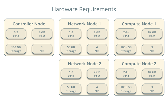
Infrastructure
- One controller node with one network interface: management.
- Two network nodes with four network interfaces: management, project tunnel networks, project VLAN networks, and external (typically the Internet). The Open vSwitch bridge br-vlan must contain a port on the VLAN interface and Open vSwitch bridge br-ex must contain a port on the external interface.
- At least one compute node with three network interfaces: management, project tunnel networks, and project VLAN networks. The Open vSwitch bridge br-vlan must contain a port on the VLAN interface.
To improve understanding of network traffic flow, the network and compute nodes contain a separate network interface for project VLAN networks. In production environments, project VLAN networks can use any Open vSwitch bridge with access to a network interface. For example, the br-tun bridge.
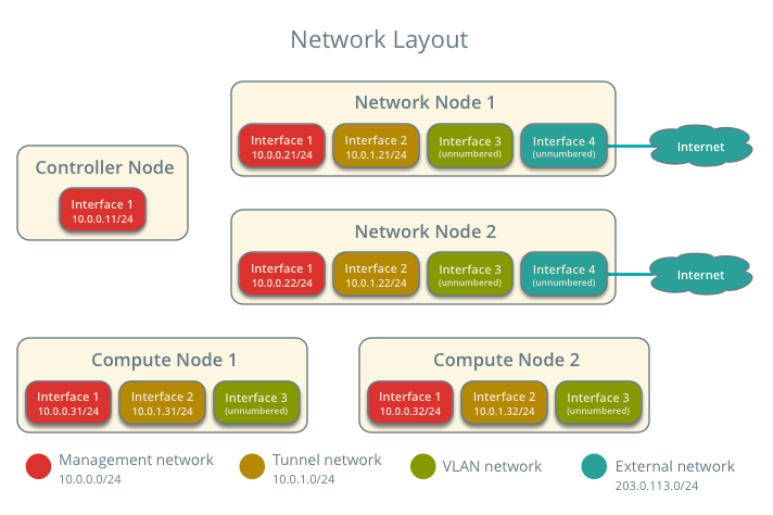
In the example configuration, the management network uses 10.0.0.0/24, the tunnel network uses 10.0.1.0/24, the VRRP network uses 169.254.192.0/18, and the external network uses 203.0.113.0/24. The VLAN network does not require an IP address range because it only handles layer-2 connectivity.
Note
For VLAN external and project networks, the network infrastructure must support VLAN tagging. For best performance with VXLAN and GRE project networks, the network infrastructure should support jumbo frames.
Warning
Linux distributions often package older releases of Open vSwitch that can introduce issues during operation with the Networking service. We recommend using at least the latest long-term stable (LTS) release of Open vSwitch for the best experience and support from Open vSwitch. See http://www.openvswitch.org for available releases and the installation instructions for building newer releases from source on various distributions.
Implementing VXLAN networks requires Linux kernel 3.13 or newer.
OpenStack services - controller node
- Operational SQL server with neutron database and appropriate configuration in the neutron.conf file.
- Operational message queue service with appropriate configuration in the neutron.conf file.
- Operational OpenStack Identity service with appropriate configuration in the neutron.conf file.
- Operational OpenStack Compute controller/management service with appropriate configuration to use OpenStack Networking in the nova.conf file.
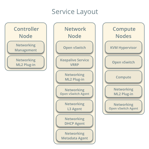
- Neutron server service, ML2 plug-in, and any dependencies.
OpenStack services - network nodes
- Operational OpenStack Identity service with appropriate configuration in the neutron.conf file.
- Open vSwitch service, ML2 plug-in, Open vSwitch agent, L3 agent, DHCP agent, metadata agent, and any dependencies.
OpenStack services - compute nodes
- Operational OpenStack Identity service with appropriate configuration in the neutron.conf file.
- Operational OpenStack Compute controller/management service with appropriate configuration to use OpenStack Networking in the neutron.conf file.
- Open vSwitch service, ML2 plug-in, Open vSwitch agent, and any dependencies.
Architecture
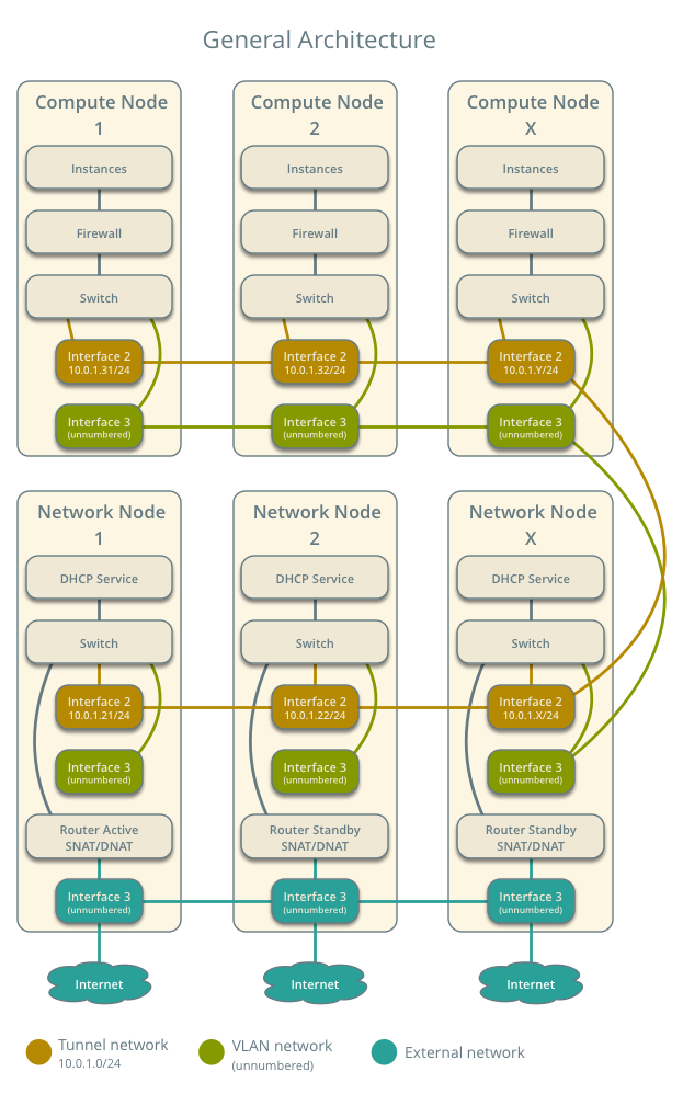
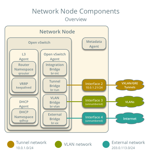
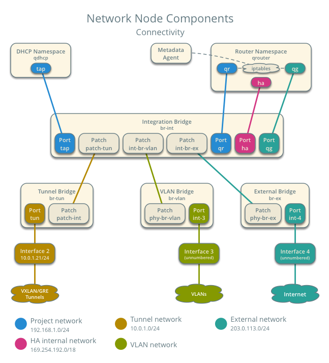
The network nodes contain the following components:
- Open vSwitch agent managing virtual switches, connectivity among them, and interaction via virtual ports with other network components such as namespaces, Linux bridges, and underlying interfaces.
- DHCP agent managing the qdhcp namespaces. The qdhcp namespaces provide DHCP services for instances using project networks.
- L3 agent managing the qrouter namespaces and VRRP using keepalived. The qrouter namespaces provide routing between project and external networks and among project networks. They also route metadata traffic between instances and the metadata agent.
- Metadata agent handling metadata operations for instances.
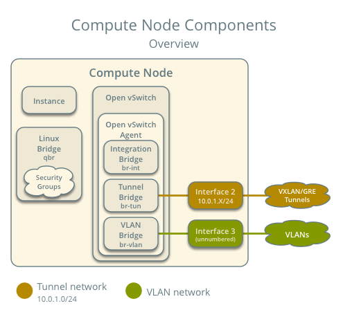
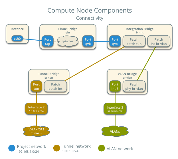
The compute nodes contain the following components:
Open vSwitch agent managing virtual switches, connectivity among them, and interaction via virtual ports with other network components such as namespaces, Linux bridges, and underlying interfaces.
Linux bridges handling security groups.
Note
Due to limitations with Open vSwitch and iptables, the Networking service uses a Linux bridge to manage security groups for instances.
Packet flow
The L3HA mechanism simply augments Scenario: Legacy with Open vSwitch with quick failover of layer-3 services to another router if the master router fails.
During normal operation, the master router periodically transmits heartbeat packets over a hidden project network that connects all HA routers for a particular project. By default, this network uses the type indicated by the first value in the tenant_network_types option in the /etc/neutron/plugins/ml2_conf.ini file.
If the backup router stops receiving these packets, it assumes failure of the master router and promotes itself to the master router by configuring IP addresses on the interfaces in the qrouter namespace. In environments with more than one backup router, the router with the next highest priority becomes the master router.
Note
The L3HA mechanism uses the same priority for all routers. Therefore, VRRP promotes the backup router with the highest IP address to the master router.
Example configuration
Use the following example configuration as a template to deploy this scenario in your environment.
Controller node
Configure common options. Edit the /etc/neutron/neutron.conf file:
[DEFAULT]
verbose = True
core_plugin = ml2
service_plugins = router
allow_overlapping_ips = True
router_distributed = False
l3_ha = True
l3_ha_net_cidr = 169.254.192.0/18
max_l3_agents_per_router = 3
min_l3_agents_per_router = 2
dhcp_agents_per_network = 2
Configure the ML2 plug-in. Edit the /etc/neutron/plugins/ml2/ml2_conf.ini file:
[ml2]
type_drivers = flat,vlan,gre,vxlan
tenant_network_types = vlan,gre,vxlan
mechanism_drivers = openvswitch

[ml2_type_flat]
flat_networks = external

[ml2_type_vlan]
network_vlan_ranges = external,vlan:MIN_VLAN_ID:MAX_VLAN_ID

[ml2_type_gre]
tunnel_id_ranges = MIN_GRE_ID:MAX_GRE_ID

[ml2_type_vxlan]
vni_ranges = MIN_VXLAN_ID:MAX_VXLAN_ID
vxlan_group = 239.1.1.1

[securitygroup]
firewall_driver = neutron.agent.linux.iptables_firewall.OVSHybridIptablesFirewallDriver
enable_security_group = True
enable_ipset = True
Replace MIN_VLAN_ID, MAX_VLAN_ID, MIN_GRE_ID, MAX_GRE_ID, MIN_VXLAN_ID, and MAX_VXLAN_ID with VLAN, GRE, and VXLAN ID minimum and maximum values suitable for your environment.
Note
The first value in the tenant_network_types option becomes the default project network type when a regular user creates a network.
Note
The external value in the network_vlan_ranges option lacks VLAN ID ranges to support use of arbitrary VLAN IDs by administrative users.
Start the following services:
- Server
Network nodes
Configure the kernel to enable packet forwarding and disable reverse path filtering. Edit the /etc/sysctl.conf file:
net.ipv4.ip_forward=1
net.ipv4.conf.default.rp_filter=0
net.ipv4.conf.all.rp_filter=0
Load the new kernel configuration:
$ sysctl -pConfigure common options. Edit the /etc/neutron/neutron.conf file:
[DEFAULT]
verbose = True
Configure the Open vSwitch agent. Edit the /etc/neutron/plugins/ml2/ml2_conf.ini file:
[ovs]
local_ip = TUNNEL_INTERFACE_IP_ADDRESS
bridge_mappings = vlan:br-vlan,external:br-ex

[agent]
tunnel_types = gre,vxlan
l2_population = False

[securitygroup]
firewall_driver = neutron.agent.linux.iptables_firewall.OVSHybridIptablesFirewallDriver
enable_security_group = True
enable_ipset = True
Replace TUNNEL_INTERFACE_IP_ADDRESS with the IP address of the interface that handles GRE/VXLAN project networks.
Configure the L3 agent. Edit the /etc/neutron/l3_agent.ini file:
[DEFAULT]
verbose = True
interface_driver = neutron.agent.linux.interface.OVSInterfaceDriver
use_namespaces = True
external_network_bridge =
router_delete_namespaces = True
agent_mode = legacy
Note
The external_network_bridge option intentionally contains no value.
Configure the DHCP agent. Edit the /etc/neutron/dhcp_agent.ini file:
[DEFAULT]
verbose = True
interface_driver = neutron.agent.linux.interface.OVSInterfaceDriver
dhcp_driver = neutron.agent.linux.dhcp.Dnsmasq
use_namespaces = True
dhcp_delete_namespaces = True
(Optional) Reduce MTU for VXLAN/GRE project networks.
Edit the /etc/neutron/dhcp_agent.ini file:
[DEFAULT]
dnsmasq_config_file = /etc/neutron/dnsmasq-neutron.conf
Edit the /etc/neutron/dnsmasq-neutron.conf file:
dhcp-option-force=26,1450
Configure the metadata agent. Edit the /etc/neutron/metadata_agent.ini file:
[DEFAULT]
verbose = True
nova_metadata_ip = controller
metadata_proxy_shared_secret = METADATA_SECRET
Replace METADATA_SECRET with a suitable value for your environment.
Start the following services:
- Open vSwitch
- Open vSwitch agent
- L3 agent
- DHCP agent
- Metadata agent
Compute nodes
Configure the kernel to enable iptables on bridges and disable reverse path filtering. Edit the /etc/sysctl.conf file:
net.ipv4.conf.default.rp_filter=0
net.ipv4.conf.all.rp_filter=0
net.bridge.bridge-nf-call-iptables=1
net.bridge.bridge-nf-call-ip6tables=1
Load the new kernel configuration:
$ sysctl -pConfigure common options. Edit the /etc/neutron/neutron.conf file:
[DEFAULT]
verbose = True
Configure the Open vSwitch agent. Edit the /etc/neutron/plugins/ml2/ml2_conf.ini file:
[ovs]
local_ip = TUNNEL_INTERFACE_IP_ADDRESS
bridge_mappings = vlan:br-vlan

[agent]
tunnel_types = gre,vxlan
l2_population = False

[securitygroup]
firewall_driver = neutron.agent.linux.iptables_firewall.OVSHybridIptablesFirewallDriver
enable_security_group = True
enable_ipset = True
Replace TUNNEL_INTERFACE_IP_ADDRESS with the IP address of the interface that handles GRE/VXLAN project networks.
Start the following services:
- Open vSwitch
- Open vSwitch agent
Verify service operation
Source the administrative project credentials.
Verify presence and operation of the agents:
$ neutron agent-list
+--------------------------------------+--------------------+----------+-------+----------------+---------------------------+
| id                                   | agent_type         | host     | alive | admin_state_up | binary                    |
+--------------------------------------+--------------------+----------+-------+----------------+---------------------------+
| 0bfe5b5d-0b82-434e-b8a0-524cc18da3a4 | DHCP agent         | network1 | :-)   | True           | neutron-dhcp-agent        |
| 25224bd5-0905-4ec9-9f2d-3b17cdaf5650 | Open vSwitch agent | compute2 | :-)   | True           | neutron-openvswitch-agent |
| 29afe014-273d-42f3-ad71-8a226e40dea6 | L3 agent           | network1 | :-)   | True           | neutron-l3-agent          |
| 3bed5093-e46c-4b0f-9460-3309c62254a3 | DHCP agent         | network2 | :-)   | True           | neutron-dhcp-agent        |
| 54aefb1c-35f7-4ebf-a848-3bb4fe81dcf7 | Open vSwitch agent | network1 | :-)   | True           | neutron-openvswitch-agent |
| 91c9cc03-1678-4d7a-b0a7-fa1ac24e5516 | Open vSwitch agent | compute1 | :-)   | True           | neutron-openvswitch-agent |
| ac7b3f77-7e4d-47a6-9dbd-3358cfb67b61 | Open vSwitch agent | network2 | :-)   | True           | neutron-openvswitch-agent |
| ceef5c49-3148-4c39-9e15-4985fc995113 | Metadata agent     | network1 | :-)   | True           | neutron-metadata-agent    |
| d27ac19b-fb4d-4fec-b81d-e8c65557b6ec | L3 agent           | network2 | :-)   | True           | neutron-l3-agent          |
| f072a1ec-f842-4223-a6b6-ec725419be85 | Metadata agent     | network2 | :-)   | True           | neutron-metadata-agent    |
+--------------------------------------+--------------------+----------+-------+----------------+---------------------------+
Create initial networks
This example creates a flat external network and a VXLAN project network.
Source the administrative project credentials.
Create the external network:
$ neutron net-create ext-net --router:external True \
  --provider:physical_network external --provider:network_type flat
Created a new network:
+---------------------------+--------------------------------------+
| Field                     | Value                                |
+---------------------------+--------------------------------------+
| admin_state_up            | True                                 |
| id                        | 5266fcbc-d429-4b21-8544-6170d1691826 |
| name                      | ext-net                              |
| provider:network_type     | flat                                 |
| provider:physical_network | external                             |
| provider:segmentation_id  |                                      |
| router:external           | True                                 |
| shared                    | False                                |
| status                    | ACTIVE                               |
| subnets                   |                                      |
| tenant_id                 | 96393622940e47728b6dcdb2ef405f50     |
+---------------------------+--------------------------------------+
Create a subnet on the external network:
$ neutron subnet-create ext-net 203.0.113.0/24 --name ext-subnet \
  --allocation-pool start=203.0.113.101,end=203.0.113.200 \
  --disable-dhcp --gateway 203.0.113.1
Created a new subnet:
+-------------------+----------------------------------------------------+
| Field             | Value                                              |
+-------------------+----------------------------------------------------+
| allocation_pools  | {"start": "203.0.113.101", "end": "203.0.113.200"} |
| cidr              | 203.0.113.0/24                                     |
| dns_nameservers   |                                                    |
| enable_dhcp       | False                                              |
| gateway_ip        | 203.0.113.1                                        |
| host_routes       |                                                    |
| id                | b32e0efc-8cc3-43ff-9899-873b94df0db1               |
| ip_version        | 4                                                  |
| ipv6_address_mode |                                                    |
| ipv6_ra_mode      |                                                    |
| name              | ext-subnet                                         |
| network_id        | 5266fcbc-d429-4b21-8544-6170d1691826               |
| tenant_id         | 96393622940e47728b6dcdb2ef405f50                   |
+-------------------+----------------------------------------------------+
Note
The example configuration contains vlan as the first project network type. Only an administrative user can create other types of networks such as GRE or VXLAN. The following commands use the admin project credentials to create a VXLAN project network.
Obtain the ID of a regular project. For example, using the demo project:
$ openstack project show demo
+-------------+----------------------------------+
|   Field     |              Value               |
+-------------+----------------------------------+
| description |           Demo Tenant            |
|   enabled   |               True               |
|      id     | 443cd1596b2e46d49965750771ebbfe1 |
|     name    |               demo               |
+-------------+----------------------------------+
Create the project network:
$ neutron net-create demo-net \
  --tenant-id 443cd1596b2e46d49965750771ebbfe1 \
  --provider:network_type vxlan
Created a new network:
+---------------------------+--------------------------------------+
| Field                     | Value                                |
+---------------------------+--------------------------------------+
| admin_state_up            | True                                 |
| id                        | 7ac9a268-1ddd-453f-857b-0fd9552b645f |
| name                      | demo-net                             |
| provider:network_type     | vxlan                                |
| provider:physical_network |                                      |
| provider:segmentation_id  | 1                                    |
| router:external           | False                                |
| shared                    | False                                |
| status                    | ACTIVE                               |
| subnets                   |                                      |
| tenant_id                 | 443cd1596b2e46d49965750771ebbfe1     |
+---------------------------+--------------------------------------+
Source the demo project credentials. The following steps use the demo project.
Create a subnet on the project network:
$ neutron subnet-create demo-net 192.168.1.0/24 --name demo-subnet \
  --gateway 192.168.1.1
Created a new subnet:
+-------------------+--------------------------------------------------+
| Field             | Value                                            |
+-------------------+--------------------------------------------------+
| allocation_pools  | {"start": "192.168.1.2", "end": "192.168.1.254"} |
| cidr              | 192.168.1.0/24                                   |
| dns_nameservers   |                                                  |
| enable_dhcp       | True                                             |
| gateway_ip        | 192.168.1.1                                      |
| host_routes       |                                                  |
| id                | 2945790c-5999-4693-b8e7-50a9fc7f46f5             |
| ip_version        | 4                                                |
| ipv6_address_mode |                                                  |
| ipv6_ra_mode      |                                                  |
| name              | demo-subnet                                      |
| network_id        | 7ac9a268-1ddd-453f-857b-0fd9552b645f             |
| tenant_id         | 443cd1596b2e46d49965750771ebbfe1                 |
+-------------------+--------------------------------------------------+
Create a project router:
$ neutron router-create demo-router
Created a new router:
+-----------------------+--------------------------------------+
| Field                 | Value                                |
+-----------------------+--------------------------------------+
| admin_state_up        | True                                 |
| distributed           | False                                |
| external_gateway_info |                                      |
| ha                    | True                                 |
| id                    | 7a46dba8-8846-498c-9e10-588664558473 |
| name                  | demo-router                          |
| routes                |                                      |
| status                | ACTIVE                               |
| tenant_id             | 443cd1596b2e46d49965750771ebbfe1     |
+-----------------------+--------------------------------------+
Note
The default policy.json file allows only administrative projects to enable/disable HA during router creation and view the ha flag for a router.
Add the project subnet as an interface on the router:
$ neutron router-interface-add demo-router demo-subnet
Added interface 8de3e172-5317-4c87-bdc1-f69e359de92e to router demo-router.
Add a gateway to the external network on the router:
$ neutron router-gateway-set demo-router ext-net
Set gateway for router demo-router
Verify network operation
Source the administrative project credentials.
On the controller node, verify creation of the HA network:
$ neutron net-list
+--------------------------------------+----------------------------------------------------+-------------------------------------------------------+
| id                                   | name                                               | subnets                                               |
+--------------------------------------+----------------------------------------------------+-------------------------------------------------------+
| 5266fcbc-d429-4b21-8544-6170d1691826 | ext-net                                            | b32e0efc-8cc3-43ff-9899-873b94df0db1 203.0.113.0/24   |
| e029b568-0fd7-4d10-bb16-f9e014811d10 | HA network tenant 443cd1596b2e46d49965750771ebbfe1 | ee30083f-eb4c-41ea-8937-1bae65740af4 169.254.192.0/18 |
| 7ac9a268-1ddd-453f-857b-0fd9552b645f | demo-net                                           | 2945790c-5999-4693-b8e7-50a9fc7f46f5 192.168.1.0/24   |
+--------------------------------------+----------------------------------------------------+-------------------------------------------------------+
On the controller node, verify creation of the router on more than one network node:
$ neutron l3-agent-list-hosting-router demo-router
+--------------------------------------+----------+----------------+-------+----------+
| id                                   | host     | admin_state_up | alive | ha_state |
+--------------------------------------+----------+----------------+-------+----------+
| 29afe014-273d-42f3-ad71-8a226e40dea6 | network1 | True           | :-)   | active   |
| d27ac19b-fb4d-4fec-b81d-e8c65557b6ec | network2 | True           | :-)   | standby  |
+--------------------------------------+----------+----------------+-------+----------+
Note
Older versions of python-neutronclient do not support the ha_state field.
On the controller node, verify creation of the HA ports on the demo-router router:
$ neutron router-port-list demo-router
+--------------------------------------+-------------------------------------------------+-------------------+----------------------------------------------------------------------------------------+
| id                                   | name                                            | mac_address       | fixed_ips                                                                              |
+--------------------------------------+-------------------------------------------------+-------------------+----------------------------------------------------------------------------------------+
| 255d2e4b-33ba-4166-a13f-6531122641fe | HA port tenant 443cd1596b2e46d49965750771ebbfe1 | fa:16:3e:25:05:d7 | {"subnet_id": "8e8e4c7d-fa38-417d-a4e3-03ee5ab5493c", "ip_address": "169.254.192.1"}   |
| 374587d7-2acd-4156-8993-4294f788b55e |                                                 | fa:16:3e:82:a0:59 | {"subnet_id": "b32e0efc-8cc3-43ff-9899-873b94df0db1", "ip_address": "203.0.113.101"}   |
| 8de3e172-5317-4c87-bdc1-f69e359de92e |                                                 | fa:16:3e:10:9f:f6 | {"subnet_id": "2945790c-5999-4693-b8e7-50a9fc7f46f5", "ip_address": "192.168.1.1"}     |
| 90d1a59f-b122-459d-a94a-162a104de629 | HA port tenant 443cd1596b2e46d49965750771ebbfe1 | fa:16:3e:ae:3b:22 | {"subnet_id": "8e8e4c7d-fa38-417d-a4e3-03ee5ab5493c", "ip_address": "169.254.192.2"}   |
+--------------------------------------+-------------------------------------------------+-------------------+----------------------------------------------------------------------------------------+
On the network nodes, verify creation of the qrouter and qdhcp namespaces:
Network node 1:
$ ip netns
qrouter-7a46dba8-8846-498c-9e10-588664558473
Network node 2:
$ ip netns
qrouter-7a46dba8-8846-498c-9e10-588664558473
Both qrouter namespaces should use the same UUID.
Note
The qdhcp namespaces might not exist until launching an instance.
On the network nodes, verify HA operation:
Network node 1:
$ ip netns exec qrouter-7a46dba8-8846-498c-9e10-588664558473 ip addr show
11: ha-255d2e4b-33: <BROADCAST,MULTICAST,UP,LOWER_UP> mtu 1500 qdisc noqueue state UNKNOWN group default
    link/ether fa:16:3e:25:05:d7 brd ff:ff:ff:ff:ff:ff
    inet 169.254.192.1/18 brd 169.254.255.255 scope global ha-255d2e4b-33
       valid_lft forever preferred_lft forever
    inet6 fe80::f816:3eff:fe25:5d7/64 scope link
       valid_lft forever preferred_lft forever
12: qr-8de3e172-53: <BROADCAST,MULTICAST,UP,LOWER_UP> mtu 1500 qdisc noqueue state UNKNOWN group default
    link/ether fa:16:3e:10:9f:f6 brd ff:ff:ff:ff:ff:ff
    inet 192.168.1.1/24 scope global qr-8de3e172-53
       valid_lft forever preferred_lft forever
    inet6 fe80::f816:3eff:fe10:9ff6/64 scope link
       valid_lft forever preferred_lft forever
13: qg-374587d7-2a: <BROADCAST,MULTICAST,UP,LOWER_UP> mtu 1500 qdisc noqueue state UNKNOWN group default
    link/ether fa:16:3e:82:a0:59 brd ff:ff:ff:ff:ff:ff
    inet 203.0.113.101/24 scope global qg-374587d7-2a
       valid_lft forever preferred_lft forever
    inet6 fe80::f816:3eff:fe82:a059/64 scope link
       valid_lft forever preferred_lft forever
Network node 2:
$ ip netns exec qrouter-7a46dba8-8846-498c-9e10-588664558473 ip addr show
11: ha-90d1a59f-b1: <BROADCAST,MULTICAST,UP,LOWER_UP> mtu 1500 qdisc noqueue state UNKNOWN group default
    link/ether fa:16:3e:ae:3b:22 brd ff:ff:ff:ff:ff:ff
    inet 169.254.192.2/18 brd 169.254.255.255 scope global ha-90d1a59f-b1
       valid_lft forever preferred_lft forever
    inet6 fe80::f816:3eff:feae:3b22/64 scope link
       valid_lft forever preferred_lft forever
12: qr-8de3e172-53: <BROADCAST,MULTICAST,UP,LOWER_UP> mtu 1500 qdisc noqueue state UNKNOWN group default
    link/ether fa:16:3e:10:9f:f6 brd ff:ff:ff:ff:ff:ff
    inet6 fe80::f816:3eff:fe10:9ff6/64 scope link
       valid_lft forever preferred_lft forever
13: qg-374587d7-2a: <BROADCAST,MULTICAST,UP,LOWER_UP> mtu 1500 qdisc noqueue state UNKNOWN group default
    link/ether fa:16:3e:82:a0:59 brd ff:ff:ff:ff:ff:ff
    inet6 fe80::f816:3eff:fe82:a059/64 scope link
       valid_lft forever preferred_lft forever
On each network node, the qrouter namespace should include the ha, qr, and qg interfaces. On the master node, the qr interface contains the project network gateway IP address and the qg interface contains the project router IP address on the external network. On the backup node, the qr and qg interfaces should not contain an IP address. On both nodes, the ha interface should contain a unique IP address in the 169.254.192.0/18 range.
On the network nodes, verify VRRP advertisements from the master node HA interface IP address on the appropriate network interface:
Network node 1:
$ tcpdump -lnpi eth1
16:50:16.857294 IP 169.254.192.1 > 224.0.0.18: VRRPv2, Advertisement, vrid 1, prio 50, authtype none, intvl 2s, length 20
16:50:18.858436 IP 169.254.192.1 > 224.0.0.18: VRRPv2, Advertisement, vrid 1, prio 50, authtype none, intvl 2s, length 20
16:50:20.859677 IP 169.254.192.1 > 224.0.0.18: VRRPv2, Advertisement, vrid 1, prio 50, authtype none, intvl 2s, length 20
Network node 2:
$ tcpdump -lnpi eth1
16:51:44.911640 IP 169.254.192.1 > 224.0.0.18: VRRPv2, Advertisement, vrid 1, prio 50, authtype none, intvl 2s, length 20
16:51:46.912591 IP 169.254.192.1 > 224.0.0.18: VRRPv2, Advertisement, vrid 1, prio 50, authtype none, intvl 2s, length 20
16:51:48.913900 IP 169.254.192.1 > 224.0.0.18: VRRPv2, Advertisement, vrid 1, prio 50, authtype none, intvl 2s, length 20
Note
The example output uses network interface eth1.
Determine the external network gateway IP address for the project network on the router, typically the lowest IP address in the external subnet IP allocation range:
$ neutron router-port-list demo-router
+--------------------------------------+-------------------------------------------------+-------------------+----------------------------------------------------------------------------------------+
| id                                   | name                                            | mac_address       | fixed_ips                                                                              |
+--------------------------------------+-------------------------------------------------+-------------------+----------------------------------------------------------------------------------------+
| 255d2e4b-33ba-4166-a13f-6531122641fe | HA port tenant 443cd1596b2e46d49965750771ebbfe1 | fa:16:3e:25:05:d7 | {"subnet_id": "8e8e4c7d-fa38-417d-a4e3-03ee5ab5493c", "ip_address": "169.254.192.1"}   |
| 374587d7-2acd-4156-8993-4294f788b55e |                                                 | fa:16:3e:82:a0:59 | {"subnet_id": "b32e0efc-8cc3-43ff-9899-873b94df0db1", "ip_address": "203.0.113.101"}   |
| 8de3e172-5317-4c87-bdc1-f69e359de92e |                                                 | fa:16:3e:10:9f:f6 | {"subnet_id": "2945790c-5999-4693-b8e7-50a9fc7f46f5", "ip_address": "192.168.1.1"}     |
| 90d1a59f-b122-459d-a94a-162a104de629 | HA port tenant 443cd1596b2e46d49965750771ebbfe1 | fa:16:3e:ae:3b:22 | {"subnet_id": "8e8e4c7d-fa38-417d-a4e3-03ee5ab5493c", "ip_address": "169.254.192.2"}   |
+--------------------------------------+-------------------------------------------------+-------------------+----------------------------------------------------------------------------------------+
On the controller node or any host with access to the external network, ping the external network gateway IP address on the project router:
$ ping -c 4 203.0.113.101
PING 203.0.113.101 (203.0.113.101) 56(84) bytes of data.
64 bytes from 203.0.113.101: icmp_req=1 ttl=64 time=0.619 ms
64 bytes from 203.0.113.101: icmp_req=2 ttl=64 time=0.189 ms
64 bytes from 203.0.113.101: icmp_req=3 ttl=64 time=0.165 ms
64 bytes from 203.0.113.101: icmp_req=4 ttl=64 time=0.216 ms

--- 203.0.113.101 ping statistics ---
4 packets transmitted, 4 received, 0% packet loss, time 2999ms
rtt min/avg/max/mdev = 0.165/0.297/0.619/0.187 ms
Source the regular project credentials. The following steps use the demo project.
Create the appropriate security group rules to allow ping and SSH access to the instance. For example:
$ nova secgroup-add-rule default icmp -1 -1 0.0.0.0/0
+-------------+-----------+---------+-----------+--------------+
| IP Protocol | From Port | To Port | IP Range  | Source Group |
+-------------+-----------+---------+-----------+--------------+
| icmp        | -1        | -1      | 0.0.0.0/0 |              |
+-------------+-----------+---------+-----------+--------------+

$ nova secgroup-add-rule default tcp 22 22 0.0.0.0/0
+-------------+-----------+---------+-----------+--------------+
| IP Protocol | From Port | To Port | IP Range  | Source Group |
+-------------+-----------+---------+-----------+--------------+
| tcp         | 22        | 22      | 0.0.0.0/0 |              |
+-------------+-----------+---------+-----------+--------------+
Launch an instance with an interface on the project network. For example, using an existing CirrOS image:
$ nova boot --flavor m1.tiny --image cirros \
  --nic net-id=7ac9a268-1ddd-453f-857b-0fd9552b645f demo-instance1
+--------------------------------------+-----------------------------------------------+
| Property                             | Value                                         |
+--------------------------------------+-----------------------------------------------+
| OS-DCF:diskConfig                    | MANUAL                                        |
| OS-EXT-AZ:availability_zone          | nova                                          |
| OS-EXT-STS:power_state               | 0                                             |
| OS-EXT-STS:task_state                | scheduling                                    |
| OS-EXT-STS:vm_state                  | building                                      |
| OS-SRV-USG:launched_at               | -                                             |
| OS-SRV-USG:terminated_at             | -                                             |
| accessIPv4                           |                                               |
| accessIPv6                           |                                               |
| adminPass                            | Z3uAd2utPUNu                                  |
| config_drive                         |                                               |
| created                              | 2015-08-10T15:06:24Z                          |
| flavor                               | m1.tiny (1)                                   |
| hostId                               |                                               |
| id                                   | 77149598-c839-400f-b948-db6993f0b40b          |
| image                                | cirros (125733d9-8d37-4d70-9a64-1c989cfa8e9c) |
| key_name                             |                                               |
| metadata                             | {}                                            |
| name                                 | demo-instance1                                |
| os-extended-volumes:volumes_attached | []                                            |
| progress                             | 0                                             |
| security_groups                      | default                                       |
| status                               | BUILD                                         |
| tenant_id                            | 443cd1596b2e46d49965750771ebbfe1              |
| updated                              | 2015-08-10T15:06:25Z                          |
| user_id                              | bdd4e165bdf94b258ddd4856340ed01c              |
+--------------------------------------+-----------------------------------------------+
Obtain console access to the instance.
Test connectivity to the project router:
$ ping -c 4 192.168.1.1
PING 192.168.1.1 (192.168.1.1) 56(84) bytes of data.
64 bytes from 192.168.1.1: icmp_req=1 ttl=64 time=0.357 ms
64 bytes from 192.168.1.1: icmp_req=2 ttl=64 time=0.473 ms
64 bytes from 192.168.1.1: icmp_req=3 ttl=64 time=0.504 ms
64 bytes from 192.168.1.1: icmp_req=4 ttl=64 time=0.470 ms

--- 192.168.1.1 ping statistics ---
4 packets transmitted, 4 received, 0% packet loss, time 2998ms
rtt min/avg/max/mdev = 0.357/0.451/0.504/0.055 ms
Test connectivity to the Internet:
$ ping -c 4 openstack.org
PING openstack.org (174.143.194.225) 56(84) bytes of data.
64 bytes from 174.143.194.225: icmp_req=1 ttl=53 time=17.4 ms
64 bytes from 174.143.194.225: icmp_req=2 ttl=53 time=17.5 ms
64 bytes from 174.143.194.225: icmp_req=3 ttl=53 time=17.7 ms
64 bytes from 174.143.194.225: icmp_req=4 ttl=53 time=17.5 ms

--- openstack.org ping statistics ---
4 packets transmitted, 4 received, 0% packet loss, time 3003ms
rtt min/avg/max/mdev = 17.431/17.575/17.734/0.143 ms
Create a floating IP address on the external network:
$ neutron floatingip-create ext-net
Created a new floatingip:
+---------------------+--------------------------------------+
| Field               | Value                                |
+---------------------+--------------------------------------+
| fixed_ip_address    |                                      |
| floating_ip_address | 203.0.113.102                        |
| floating_network_id | 5266fcbc-d429-4b21-8544-6170d1691826 |
| id                  | 20a6b5dd-1c5c-460e-8a81-8b5cf1739307 |
| port_id             |                                      |
| router_id           |                                      |
| status              | DOWN                                 |
| tenant_id           | 443cd1596b2e46d49965750771ebbfe1     |
+---------------------+--------------------------------------+
Associate the floating IP address with the instance:
$ nova floating-ip-associate demo-instance1 203.0.113.102Verify addition of the floating IP address to the instance:
$ nova list
+--------------------------------------+----------------+--------+------------+-------------+-----------------------------------------+
| ID                                   | Name           | Status | Task State | Power State | Networks                                |
+--------------------------------------+----------------+--------+------------+-------------+-----------------------------------------+
| 77149598-c839-400f-b948-db6993f0b40b | demo-instance1 | ACTIVE | -          | Running     | demo-net=192.168.1.3, 203.0.113.102     |
+--------------------------------------+----------------+--------+------------+-------------+-----------------------------------------+
On the controller node or any host with access to the external network, ping the floating IP address associated with the instance:
$ ping -c 4 203.0.113.102
PING 203.0.113.102 (203.0.113.112) 56(84) bytes of data.
64 bytes from 203.0.113.102: icmp_req=1 ttl=63 time=3.18 ms
64 bytes from 203.0.113.102: icmp_req=2 ttl=63 time=0.981 ms
64 bytes from 203.0.113.102: icmp_req=3 ttl=63 time=1.06 ms
64 bytes from 203.0.113.102: icmp_req=4 ttl=63 time=0.929 ms

--- 203.0.113.102 ping statistics ---
4 packets transmitted, 4 received, 0% packet loss, time 3002ms
rtt min/avg/max/mdev = 0.929/1.539/3.183/0.951 ms

Except where otherwise noted, this document is licensed under Creative Commons Attribution 3.0 License. See all OpenStack Legal Documents.