Contents
Scenario: Legacy with Open vSwitch
This scenario describes a legacy (basic) implementation of the OpenStack Networking service using the ML2 plug-in with Open vSwitch (OVS).
The legacy implementation contributes the networking portion of self-service virtual data center infrastructure by providing a method for regular (non-privileged) users to manage virtual networks within a project and includes the following components:
Project (tenant) networks
Project networks provide connectivity to instances for a particular project. Regular (non-privileged) users can manage project networks within the allocation that an administrator or operator defines for for them. Project networks can use VLAN, GRE, or VXLAN transport methods depending on the allocation. Project networks generally use private IP address ranges (RFC1918) and lack connectivity to external networks such as the Internet. Networking refers to IP addresses on project networks as fixed IP addresses.
External networks
External networks provide connectivity to external networks such as the Internet. Only administrative (privileged) users can manage external networks because they interface with the physical network infrastructure. External networks can use flat or VLAN transport methods depending on the physical network infrastructure and generally use public IP address ranges.
Note
A flat network essentially uses the untagged or native VLAN. Similar to layer-2 properties of physical networks, only one flat network can exist per external bridge. In most cases, production deployments should use VLAN transport for external networks.
Routers
Routers typically connect project and external networks. By default, they implement SNAT to provide outbound external connectivity for instances on project networks. Each router uses an IP address in the external network allocation for SNAT. Routers also use DNAT to provide inbound external connectivity for instances on project networks. Networking refers to IP addresses on routers that provide inbound external connectivity for instances on project networks as floating IP addresses. Routers can also connect project networks that belong to the same project.
Supporting services
Other supporting services include DHCP and metadata. The DHCP service manages IP addresses for instances on project networks. The metadata service provides an API for instances on project networks to obtain metadata such as SSH keys.
The example configuration creates one flat external network and one VXLAN project (tenant) network. However, this configuration also supports VLAN external networks, VLAN project networks, and GRE project networks.
Prerequisites
These prerequisites define the minimal physical infrastructure and immediate OpenStack service dependencies necessary to deploy this scenario. For example, the Networking service immediately depends on the Identity service and the Compute service immediately depends on the Networking service. These dependencies lack services such as the Image service because the Networking service does not immediately depend on it. However, the Compute service depends on the Image service to launch an instance. The example configuration in this scenario assumes basic configuration knowledge of Networking service components.
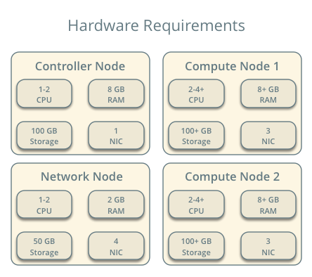
Infrastructure
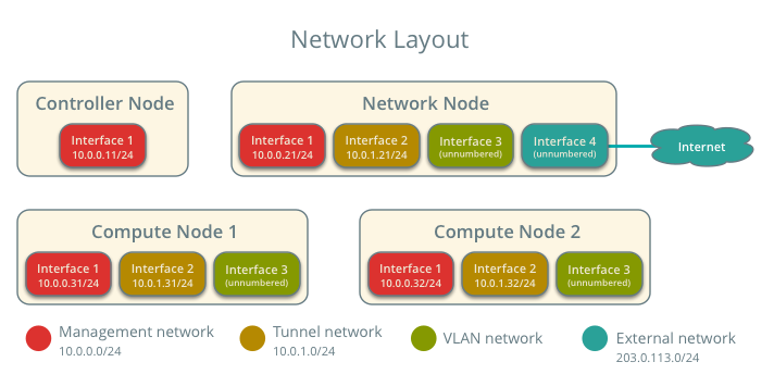
- One controller node with one network interface: management.
- One network node with four network interfaces: management, project tunnel networks, VLAN project networks, and external (typically the Internet). The Open vSwitch bridge br-vlan must contain a port on the VLAN interface and Open vSwitch bridge br-ex must contain a port on the external interface.
- At least one compute node with three network interfaces: management, project tunnel networks, and VLAN project networks. The Open vSwitch bridge br-vlan must contain a port on the VLAN interface.
To improve understanding of network traffic flow, the network and compute nodes contain a separate network interface for VLAN project networks. In production environments, VLAN project networks can use any Open vSwitch bridge with access to a network interface. For example, the br-tun bridge.
In the example configuration, the management network uses 10.0.0.0/24, the tunnel network uses 10.0.1.0/24, and the external network uses 203.0.113.0/24. The VLAN network does not require an IP address range because it only handles layer-2 connectivity.
Note
For VLAN external and project networks, the physical network infrastructure must support VLAN tagging. For best performance with VXLAN and GRE project networks, the network infrastructure should support jumbo frames.
Warning
Linux distributions often package older releases of Open vSwitch that can introduce issues during operation with the Networking service. We recommend using at least the latest long-term stable (LTS) release of Open vSwitch for the best experience and support from Open vSwitch. See http://www.openvswitch.org for available releases and the installation instructions for building newer releases from source on various distributions.
Implementing VXLAN networks requires Linux kernel 3.13 or newer.
OpenStack services - controller node
- Operational SQL server with neutron database and appropriate configuration in the neutron.conf file.
- Operational message queue service with appropriate configuration in the neutron.conf file.
- Operational OpenStack Identity service with appropriate configuration in the neutron.conf file.
- Operational OpenStack Compute controller/management service with appropriate configuration to use neutron in the nova.conf file.
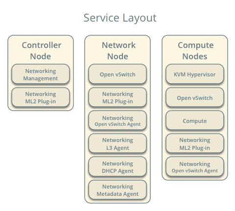
- Neutron server service, ML2 plug-in, and any dependencies.
OpenStack services - network node
- Operational OpenStack Identity service with appropriate configuration in the neutron.conf file.
- Open vSwitch service, ML2 plug-in, Open vSwitch agent, L3 agent, DHCP agent, metadata agent, and any dependencies.
OpenStack services - compute nodes
- Operational OpenStack Identity service with appropriate configuration in the neutron.conf file.
- Operational OpenStack Compute controller/management service with appropriate configuration to use neutron in the nova.conf file.
- Open vSwitch service, ML2 plug-in, Open vSwitch agent, and any dependencies.
Architecture
The legacy architecture provides basic virtual networking components in your environment. Routing among project and external networks resides completely on the network node. Although more simple to deploy than other architectures, performing all functions on the network node creates a single point of failure and potential performance issues. Consider deploying DVR or L3 HA architectures in production environments to provide redundancy and increase performance.
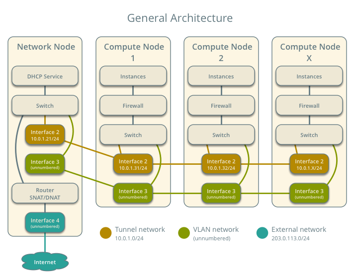
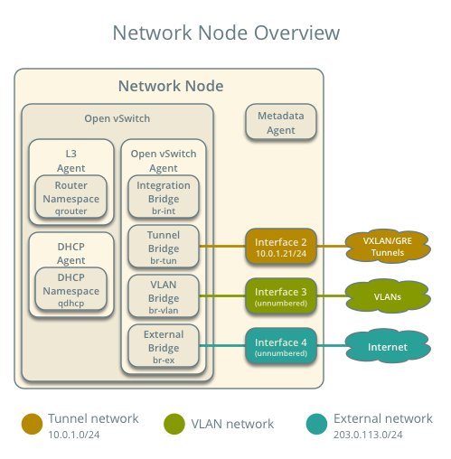
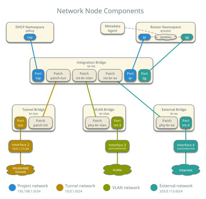
The network node contains the following network components:
- Open vSwitch agent managing virtual switches, connectivity among them, and interaction via virtual ports with other network components such as namespaces, Linux bridges, and underlying interfaces.
- DHCP agent managing the qdhcp namespaces. The qdhcp namespaces provide DHCP services for instances using project networks.
- L3 agent managing the qrouter namespaces. The qrouter namespaces provide routing between project and external networks and among project networks. They also route metadata traffic between instances and the metadata agent.
- Metadata agent handling metadata operations for instances.
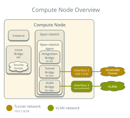
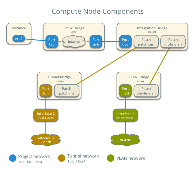
The compute nodes contain the following network components:
- Open vSwitch agent managing virtual switches, connectivity among them, and interaction via virtual ports with other network components such as namespaces, Linux bridges, and underlying interfaces.
- Linux bridges handling security groups. Due to limitations with Open vSwitch and iptables, the Networking service uses a Linux bridge to manage security groups for instances.
Packet flow
Note
North-south network traffic travels between an instance and external network, typically the Internet. East-west network traffic travels between instances.
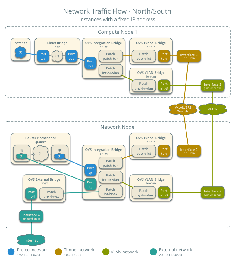
Case 1: North-south for instances with a fixed IP address
For instances with a fixed IP address, the network node routes north-south network traffic between project and external networks.
- External network
- Network 203.0.113.0/24
- IP address allocation from 203.0.113.101 to 203.0.113.200
- Project network router interface 203.0.113.101 TR
- Project network
- Network 192.168.1.0/24
- Gateway 192.168.1.1 with MAC address TG
- Compute node 1
- Instance 1 192.168.1.11 with MAC address I1
- Instance 1 resides on compute node 1 and uses a project network.
- The instance sends a packet to a host on the external network.
The following steps involve compute node 1:
- The instance 1 tap interface (1) forwards the packet to the Linux bridge qbr. The packet contains destination MAC address TG because the destination resides on another network.
- Security group rules (2) on the Linux bridge qbr handle state tracking for the packet.
- The Linux bridge qbr forwards the packet to the Open vSwitch integration bridge br-int.
- The Open vSwitch integration bridge br-int adds the internal tag for the project network.
- For VLAN project networks:
- The Open vSwitch integration bridge br-int forwards the packet to the Open vSwitch VLAN bridge br-vlan.
- The Open vSwitch VLAN bridge br-vlan replaces the internal tag with the actual VLAN tag of the project network.
- The Open vSwitch VLAN bridge br-vlan forwards the packet to the network node via the VLAN interface.
- For VXLAN and GRE project networks:
- The Open vSwitch integration bridge br-int forwards the packet to the Open vSwitch tunnel bridge br-tun.
- The Open vSwitch tunnel bridge br-tun wraps the packet in a VXLAN or GRE tunnel and adds a tag to identify the project network.
- The Open vSwitch tunnel bridge br-tun forwards the packet to the network node via the tunnel interface.
The following steps involve the network node:
- For VLAN project networks:
- The VLAN interface forwards the packet to the Open vSwitch VLAN bridge br-vlan.
- The Open vSwitch VLAN bridge br-vlan forwards the packet to the Open vSwitch integration bridge br-int.
- The Open vSwitch integration bridge br-int replaces the actual VLAN tag of the project network with the internal tag.
- For VXLAN and GRE project networks:
- The tunnel interface forwards the packet to the Open vSwitch tunnel bridge br-tun.
- The Open vSwitch tunnel bridge br-tun unwraps the packet and adds the internal tag for the project network.
- The Open vSwitch tunnel bridge br-tun forwards the packet to the Open vSwitch integration bridge br-int.
- The Open vSwitch integration bridge br-int forwards the packet to the qr interface (3) in the router namespace qrouter. The qr interface contains the project network gateway IP address TG.
- The iptables service (4) performs SNAT on the packet using the qg interface (5) as the source IP address. The qg interface contains the project network router interface IP address TR.
- The router namespace qrouter forwards the packet to the Open vSwitch integration bridge br-int via the qg interface.
- The Open vSwitch integration bridge br-int forwards the packet to the Open vSwitch external bridge br-ex.
- The Open vSwitch external bridge br-ex forwards the packet to the external network via the external interface.
Note
Return traffic follows similar steps in reverse.
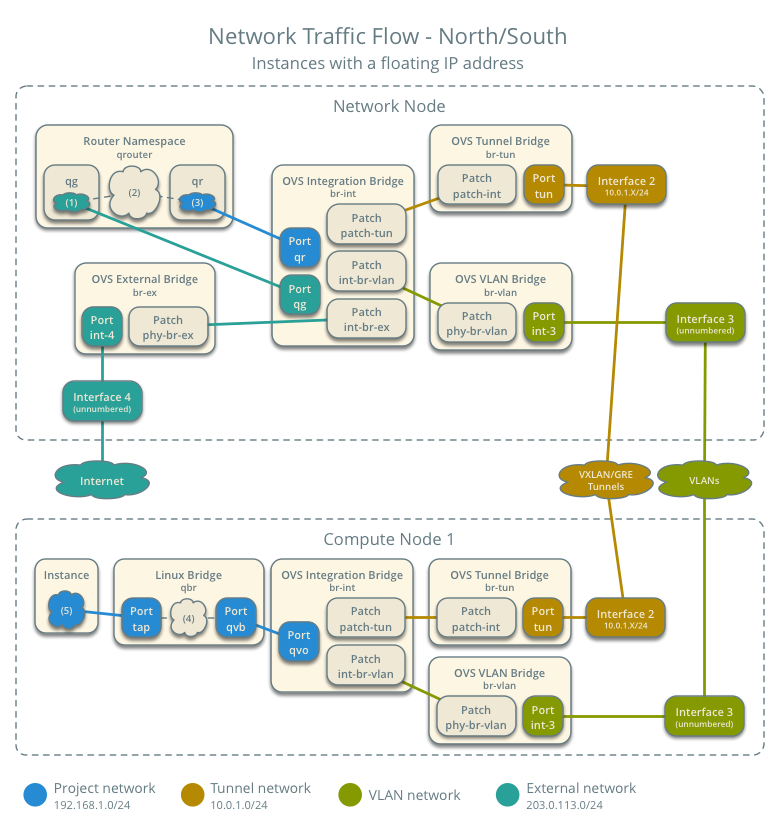
Case 2: North-south for instances with a floating IP address
For instances with a floating IP address, the network node routes north-south network traffic between project and external networks.
- External network
- Network 203.0.113.0/24
- IP address allocation from 203.0.113.101 to 203.0.113.200
- Project network router interface 203.0.113.101 TR
- Project network
- Network 192.168.1.0/24
- Gateway 192.168.1.1 with MAC address TG
- Compute node 1
- Instance 1 192.168.1.11 with MAC address I1 and floating IP address 203.0.113.102 F1
- Instance 1 resides on compute node 1 and uses a project network.
- The instance receives a packet from a host on the external network.
The following steps involve the network node:
- The external interface forwards the packet to the Open vSwitch external bridge br-ex.
- The Open vSwitch external bridge br-ex forwards the packet to the Open vSwitch integration bridge br-int.
- The Open vSwitch integration bridge forwards the packet to the qg interface (1) in the router namespace qrouter. The qg interface contains the instance 1 floating IP address F1.
- The iptables service (2) performs DNAT on the packet using the qr interface (3) as the source IP address. The qr interface contains the project network router interface IP address TR1.
- The router namespace qrouter forwards the packet to the Open vSwitch integration bridge br-int.
- The Open vSwitch integration bridge br-int adds the internal tag for the project network.
- For VLAN project networks:
- The Open vSwitch integration bridge br-int forwards the packet to the Open vSwitch VLAN bridge br-vlan.
- The Open vSwitch VLAN bridge br-vlan replaces the internal tag with the actual VLAN tag of the project network.
- The Open vSwitch VLAN bridge br-vlan forwards the packet to the compute node via the VLAN interface.
- For VXLAN and GRE project networks:
- The Open vSwitch integration bridge br-int forwards the packet to the Open vSwitch tunnel bridge br-tun.
- The Open vSwitch tunnel bridge br-tun wraps the packet in a VXLAN or GRE tunnel and adds a tag to identify the project network.
- The Open vSwitch tunnel bridge br-tun forwards the packet to the compute node via the tunnel interface.
The following steps involve compute node 1:
- For VLAN project networks:
- The VLAN interface forwards the packet to the Open vSwitch VLAN bridge br-vlan.
- The Open vSwitch VLAN bridge br-vlan forwards the packet to the Open vSwitch integration bridge br-int.
- The Open vSwitch integration bridge br-int replaces the actual VLAN tag the project network with the internal tag.
- For VXLAN and GRE project networks:
- The tunnel interface forwards the packet to the Open vSwitch tunnel bridge br-tun.
- The Open vSwitch tunnel bridge br-tun unwraps the packet and adds the internal tag for the project network.
- The Open vSwitch tunnel bridge br-tun forwards the packet to the Open vSwitch integration bridge br-int.
- The Open vSwitch integration bridge br-int forwards the packet to the Linux bridge qbr.
- Security group rules (4) on the Linux bridge qbr handle firewalling and state tracking for the packet.
- The Linux bridge qbr forwards the packet to the tap interface (5) on instance 1.
Note
Return traffic follows similar steps in reverse.
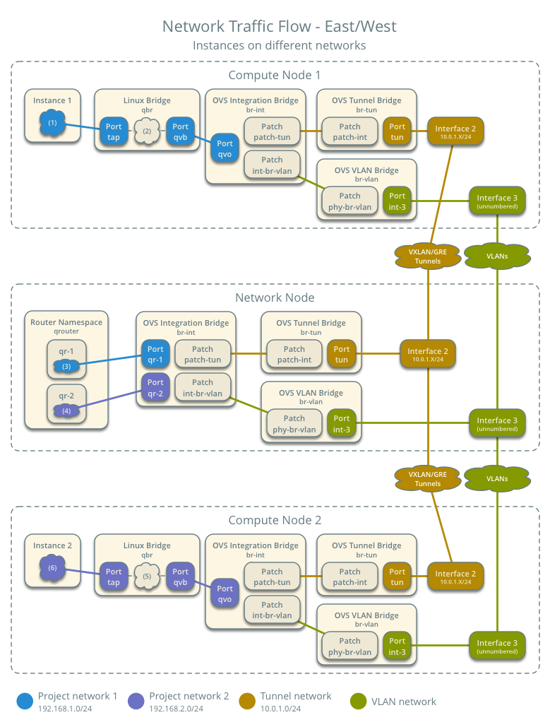
Case 3: East-west for instances on different networks
For instances with a fixed or floating IP address, the network node routes east-west network traffic among project networks using the same project router.
- Project network 1
- Network: 192.168.1.0/24
- Gateway: 192.168.1.1 with MAC address TG1
- Project network 2
- Network: 192.168.2.0/24
- Gateway: 192.168.2.1 with MAC address TG2
- Compute node 1
- Instance 1: 192.168.1.11 with MAC address I1
- Compute node 2
- Instance 2: 192.168.2.11 with MAC address I2
- Instance 1 resides on compute node 1 and uses project network 1.
- Instance 2 resides on compute node 2 and uses project network 2.
- Both project networks reside on the same router.
- Instance 1 sends a packet to instance 2.
The following steps involve compute node 1:
- The instance 1 tap interface (1) forwards the packet to the Linux bridge qbr. The packet contains destination MAC address TG1 because the destination resides on another network.
- Security group rules (2) on the Linux bridge qbr handle state tracking for the packet.
- The Linux bridge qbr forwards the packet to the Open vSwitch integration bridge br-int.
- The Open vSwitch integration bridge br-int adds the internal tag for project network 1.
- For VLAN project networks:
- The Open vSwitch integration bridge br-int forwards the packet to the Open vSwitch VLAN bridge br-vlan.
- The Open vSwitch VLAN bridge br-vlan replaces the internal tag with the actual VLAN tag of project network 1.
- The Open vSwitch VLAN bridge br-vlan forwards the packet to the network node via the VLAN interface.
- For VXLAN and GRE project networks:
- The Open vSwitch integration bridge br-int forwards the packet to the Open vSwitch tunnel bridge br-tun.
- The Open vSwitch tunnel bridge br-tun wraps the packet in a VXLAN or GRE tunnel and adds a tag to identify project network 1.
- The Open vSwitch tunnel bridge br-tun forwards the packet to the network node via the tunnel interface.
The following steps involve the network node:
- For VLAN project networks:
- The VLAN interface forwards the packet to the Open vSwitch VLAN bridge br-vlan.
- The Open vSwitch VLAN bridge br-vlan forwards the packet to the Open vSwitch integration bridge br-int.
- The Open vSwitch integration bridge br-int replaces the actual VLAN tag of project network 1 with the internal tag.
- For VXLAN and GRE project networks:
- The tunnel interface forwards the packet to the Open vSwitch tunnel bridge br-tun.
- The Open vSwitch tunnel bridge br-tun unwraps the packet and adds the internal tag for project network 1.
- The Open vSwitch tunnel bridge br-tun forwards the packet to the Open vSwitch integration bridge br-int.
- The Open vSwitch integration bridge br-int forwards the packet to the qr-1 interface (3) in the router namespace qrouter. The qr-1 interface contains the project network 1 gateway IP address TG1.
- The router namespace qrouter routes the packet to the qr-2 interface (4). The qr-2 interface contains the project network 2 gateway IP address TG2.
- The router namespace qrouter forwards the packet to the Open vSwitch integration bridge br-int.
- The Open vSwitch integration bridge br-int adds the internal tag for project network 2.
- For VLAN project networks:
- The Open vSwitch integration bridge br-int forwards the packet to the Open vSwitch VLAN bridge br-vlan.
- The Open vSwitch VLAN bridge br-vlan replaces the internal tag with the actual VLAN tag of project network 2.
- The Open vSwitch VLAN bridge br-vlan forwards the packet to compute node 2 via the VLAN interface.
- For VXLAN and GRE project networks:
- The Open vSwitch integration bridge br-int forwards the packet to the Open vSwitch tunnel bridge br-tun.
- The Open vSwitch tunnel bridge br-tun wraps the packet in a VXLAN or GRE tunnel and adds a tag to identify project network 2.
- The Open vSwitch tunnel bridge br-tun forwards the packet to compute node 2 via the tunnel interface.
The following steps involve compute node 2:
- For VLAN project networks:
- The VLAN interface forwards the packet to the Open vSwitch VLAN bridge br-vlan.
- The Open vSwitch VLAN bridge br-vlan forwards the packet to the Open vSwitch integration bridge br-int.
- The Open vSwitch integration bridge br-int replaces the actual VLAN tag of project network 2 with the internal tag.
- For VXLAN and GRE project networks:
- The tunnel interface forwards the packet to the Open vSwitch tunnel bridge br-tun.
- The Open vSwitch tunnel bridge br-tun unwraps the packet and adds the internal tag for project network 2.
- The Open vSwitch tunnel bridge br-tun forwards the packet to the Open vSwitch integration bridge br-int.
- The Open vSwitch integration bridge br-int forwards the packet to the Linux bridge qbr.
- Security group rules (5) on the Linux bridge qbr handle firewalling and state tracking for the packet.
- The Linux bridge qbr forwards the packet to the tap interface (6) on instance 2.
Note
Return traffic follows similar steps in reverse.
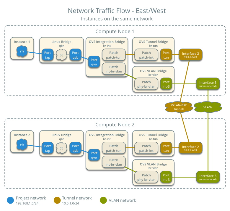
Case 4: East-west for instances on the same network
For instances with a fixed or floating IP address, the project network switches east-west network traffic among instances without using a project router on the network node.
- Project network
- Network: 192.168.1.0/24
- Compute node 1
- Instance 1: 192.168.1.11 with MAC address I1
- Compute node 2
- Instance 2: 192.168.1.12 with MAC address I2
- Instance 1 resides on compute node 1.
- Instance 2 resides on compute node 2.
- Both instances use the same project network.
- Instance 1 sends a packet to instance 2.
- The Open vSwitch agent handles switching within the project network.
The following steps involve compute node 1:
- The instance 1 tap interface (1) forwards the packet to the VLAN bridge qbr. The packet contains destination MAC address I2 because the destination resides on the same network.
- Security group rules (2) on the provider bridge qbr handle state tracking for the packet.
- The Linux bridge qbr forwards the packet to the Open vSwitch integration bridge br-int.
- The Open vSwitch integration bridge br-int adds the internal tag for provider network 1.
- For VLAN project networks:
- The Open vSwitch integration bridge br-int forwards the packet to the Open vSwitch VLAN bridge br-vlan.
- The Open vSwitch VLAN bridge br-vlan replaces the internal tag with the actual VLAN tag of project network 1.
- The Open vSwitch VLAN bridge br-vlan forwards the packet to the compute node 2 via the VLAN interface.
- For VXLAN and GRE project networks:
- The Open vSwitch integration bridge br-int forwards the packet to the Open vSwitch tunnel bridge br-tun.
- The Open vSwitch tunnel bridge br-tun wraps the packet in a VXLAN or GRE tunnel and adds a tag to identify project network 1.
- The Open vSwitch tunnel bridge br-tun forwards the packet to the compute node 2 via the tunnel interface.
The following steps involve compute node 2:
- For VLAN project networks:
- The VLAN interface forwards the packet to the Open vSwitch VLAN bridge br-vlan.
- The Open vSwitch VLAN bridge br-vlan forwards the packet to the Open vSwitch integration bridge br-int.
- The Open vSwitch integration bridge br-int replaces the actual VLAN tag of project network 2 with the internal tag.
- For VXLAN and GRE project networks:
- The tunnel interface forwards the packet to the Open vSwitch tunnel bridge br-tun.
- The Open vSwitch tunnel bridge br-tun unwraps the packet and adds the internal tag for project network 2.
- The Open vSwitch tunnel bridge br-tun forwards the packet to the Open vSwitch integration bridge br-int.
- The Open vSwitch integration bridge br-int forwards the packet to the Linux bridge qbr.
- Security group rules (3) on the Linux bridge qbr handle firewalling and state tracking for the packet.
- The Linux bridge qbr forwards the packet to the tap interface (4) on instance 2.
Note
Return traffic follows similar steps in reverse.
Example configuration
Use the following example configuration as a template to deploy this scenario in your environment.
Controller node
Configure common options. Edit the /etc/neutron/neutron.conf file:
[DEFAULT]
verbose = True
core_plugin = ml2
service_plugins = router
allow_overlapping_ips = True
Configure the ML2 plug-in. Edit the /etc/neutron/plugins/ml2/ml2_conf.ini file:
[ml2]
type_drivers = flat,vlan,gre,vxlan
tenant_network_types = vlan,gre,vxlan
mechanism_drivers = openvswitch,l2population

[ml2_type_flat]
flat_networks = external

[ml2_type_vlan]
network_vlan_ranges = external,vlan:MIN_VLAN_ID:MAX_VLAN_ID

[ml2_type_gre]
tunnel_id_ranges = MIN_GRE_ID:MAX_GRE_ID

[ml2_type_vxlan]
vni_ranges = MIN_VXLAN_ID:MAX_VXLAN_ID
vxlan_group = 239.1.1.1

[securitygroup]
firewall_driver = neutron.agent.linux.iptables_firewall.OVSHybridIptablesFirewallDriver
enable_security_group = True
enable_ipset = True
Replace MIN_VLAN_ID, MAX_VLAN_ID, MIN_GRE_ID, MAX_GRE_ID, MIN_VXLAN_ID, and MAX_VXLAN_ID with VLAN, GRE, and VXLAN ID minimum and maximum values suitable for your environment.
Note
The first value in the tenant_network_types option becomes the default project network type when a regular user creates a network.
Note
The external value in the network_vlan_ranges option lacks VLAN ID ranges to support use of arbitrary VLAN IDs by administrative users.
Start the following services:
- Server
Network node
Configure the kernel to enable packet forwarding and disable reverse path filtering. Edit the /etc/sysctl.conf file:
net.ipv4.ip_forward=1
net.ipv4.conf.default.rp_filter=0
net.ipv4.conf.all.rp_filter=0
Load the new kernel configuration:
$ sysctl -pConfigure common options. Edit the /etc/neutron/neutron.conf file:
[DEFAULT]
verbose = True
Configure the Open vSwitch agent. Edit the /etc/neutron/plugins/ml2/ml2_conf.ini file:
[ovs]
local_ip = TUNNEL_INTERFACE_IP_ADDRESS
enable_tunneling = True
bridge_mappings = vlan:br-vlan,external:br-ex

[agent]
l2_population = True
tunnel_types = gre,vxlan

[securitygroup]
firewall_driver = neutron.agent.linux.iptables_firewall.OVSHybridIptablesFirewallDriver
enable_security_group = True
enable_ipset = True
Replace TUNNEL_INTERFACE_IP_ADDRESS with the IP address of the interface that handles GRE/VXLAN project networks.
Configure the L3 agent. Edit the /etc/neutron/l3_agent.ini file:
[DEFAULT]
verbose = True
interface_driver = neutron.agent.linux.interface.OVSInterfaceDriver
use_namespaces = True
external_network_bridge =
router_delete_namespaces = True
Note
The external_network_bridge option intentionally contains no value.
Configure the DHCP agent. Edit the /etc/neutron/dhcp_agent.ini file:
[DEFAULT]
verbose = True
interface_driver = neutron.agent.linux.interface.OVSInterfaceDriver
dhcp_driver = neutron.agent.linux.dhcp.Dnsmasq
use_namespaces = True
dhcp_delete_namespaces = True
(Optional) Reduce MTU for VXLAN/GRE project networks.
Edit the /etc/neutron/dhcp_agent.ini file:
[DEFAULT]
dnsmasq_config_file = /etc/neutron/dnsmasq-neutron.conf
Edit the /etc/neutron/dnsmasq-neutron.conf file:
dhcp-option-force=26,1450
Configure the metadata agent. Edit the /etc/neutron/metadata_agent.ini file:
[DEFAULT]
verbose = True
nova_metadata_ip = controller
metadata_proxy_shared_secret = METADATA_SECRET
Replace METADATA_SECRET with a suitable value for your environment.
Start the following services:
- Open vSwitch
- Open vSwitch agent
- L3 agent
- DHCP agent
- Metadata agent
Compute nodes
Configure the kernel to enable iptables on bridges and disable reverse path filtering. Edit the /etc/sysctl.conf file:
net.ipv4.conf.default.rp_filter=0
net.ipv4.conf.all.rp_filter=0
net.bridge.bridge-nf-call-iptables=1
net.bridge.bridge-nf-call-ip6tables=1
Load the new kernel configuration:
$ sysctl -pConfigure common options. Edit the /etc/neutron/neutron.conf file:
[DEFAULT]
verbose = True
Configure the Open vSwitch agent. Edit the /etc/neutron/plugins/ml2/ml2_conf.ini file:
[ovs]
local_ip = TUNNEL_INTERFACE_IP_ADDRESS
enable_tunneling = True
bridge_mappings = vlan:br-vlan

[agent]
l2_population = True
tunnel_types = gre,vxlan

[securitygroup]
firewall_driver = neutron.agent.linux.iptables_firewall.OVSHybridIptablesFirewallDriver
enable_security_group = True
enable_ipset = True
Replace TUNNEL_INTERFACE_IP_ADDRESS with the IP address of the interface that handles GRE/VXLAN project networks.
Start the following services:
- Open vSwitch
- Open vSwitch agent
Verify service operation
Source the administrative project credentials.
Verify presence and operation of the agents:
$ neutron agent-list
+--------------------------------------+--------------------+----------+-------+----------------+---------------------------+
| id                                   | agent_type         | host     | alive | admin_state_up | binary                    |
+--------------------------------------+--------------------+----------+-------+----------------+---------------------------+
| 1eaf6079-41c8-4b5b-876f-73b02753ff57 | Open vSwitch agent | compute1 | :-)   | True           | neutron-openvswitch-agent |
| 511c27b3-8317-4e27-8a0f-b158e4fb8368 | Metadata agent     | network1 | :-)   | True           | neutron-metadata-agent    |
| 7eae11ef-8157-4fd4-a352-bc841cf709f6 | Open vSwitch agent | network1 | :-)   | True           | neutron-openvswitch-agent |
| a9110ce6-22cc-4f78-9b2e-57f83aac68a3 | Open vSwitch agent | compute2 | :-)   | True           | neutron-openvswitch-agent |
| c41f3200-8eda-43ab-8135-573e826776d9 | DHCP agent         | network1 | :-)   | True           | neutron-dhcp-agent        |
| f897648e-7623-486c-8043-1b219eb2895a | L3 agent           | network1 | :-)   | True           | neutron-l3-agent          |
+--------------------------------------+--------------------+----------+-------+----------------+---------------------------+
Create initial networks
This example creates a flat external network and a VXLAN project network.
Source the administrative project credentials.
Create the external network:
$ neutron net-create ext-net --router:external True \
  --provider:physical_network external --provider:network_type flat
  Created a new network:
+---------------------------+--------------------------------------+
| Field                     | Value                                |
+---------------------------+--------------------------------------+
| admin_state_up            | True                                 |
| id                        | e5f9be2f-3332-4f2d-9f4d-7f87a5a7692e |
| name                      | ext-net                              |
| provider:network_type     | flat                                 |
| provider:physical_network | external                             |
| provider:segmentation_id  |                                      |
| router:external           | True                                 |
| shared                    | False                                |
| status                    | ACTIVE                               |
| subnets                   |                                      |
| tenant_id                 | 96393622940e47728b6dcdb2ef405f50     |
+---------------------------+--------------------------------------+
Create a subnet on the external network:
$ neutron subnet-create ext-net --name ext-subnet --allocation-pool \
  start=203.0.113.101,end=203.0.113.200 --disable-dhcp \
  --gateway 203.0.113.1 203.0.113.0/24
Created a new subnet:
+-------------------+----------------------------------------------------+
| Field             | Value                                              |
+-------------------+----------------------------------------------------+
| allocation_pools  | {"start": "203.0.113.101", "end": "203.0.113.200"} |
| cidr              | 203.0.113.0/24                                     |
| dns_nameservers   |                                                    |
| enable_dhcp       | False                                              |
| gateway_ip        | 203.0.113.1                                        |
| host_routes       |                                                    |
| id                | cd9c15a1-0a66-4bbe-b1b4-4b7edd936f7a               |
| ip_version        | 4                                                  |
| ipv6_address_mode |                                                    |
| ipv6_ra_mode      |                                                    |
| name              | ext-subnet                                         |
| network_id        | e5f9be2f-3332-4f2d-9f4d-7f87a5a7692e               |
| tenant_id         | 96393622940e47728b6dcdb2ef405f50                   |
+-------------------+----------------------------------------------------+
Note
The example configuration contains vlan as the first project network type. Only an administrative user can create other types of networks such as GRE or VXLAN. The following commands use the admin project credentials to create a VXLAN project network.
Obtain the ID of a regular project. For example, using the demo project:
$ openstack project show demo
+-------------+----------------------------------+
| Field       | Value                            |
+-------------+----------------------------------+
| description | Demo Project                     |
| enabled     | True                             |
| id          | 443cd1596b2e46d49965750771ebbfe1 |
| name        | demo                             |
+-------------+----------------------------------+
Create the project network:
$ neutron net-create demo-net --tenant-id 443cd1596b2e46d49965750771ebbfe1 \
  --provider:network_type vxlan
Created a new network:
+---------------------------+--------------------------------------+
| Field                     | Value                                |
+---------------------------+--------------------------------------+
| admin_state_up            | True                                 |
| id                        | 6e9c5324-68d1-47a8-98d5-8268db955475 |
| name                      | demo-net                             |
| provider:network_type     | vxlan                                |
| provider:physical_network |                                      |
| provider:segmentation_id  | 1                                    |
| router:external           | False                                |
| shared                    | False                                |
| status                    | ACTIVE                               |
| subnets                   |                                      |
| tenant_id                 | 443cd1596b2e46d49965750771ebbfe1     |
+---------------------------+--------------------------------------+
Source the regular project credentials. The following steps use the demo project.
Create a subnet on the project network:
$ neutron subnet-create demo-net --name demo-subnet --gateway 192.168.1.1 \
  192.168.1.0/24
Created a new subnet:
+-------------------+--------------------------------------------------+
| Field             | Value                                            |
+-------------------+--------------------------------------------------+
| allocation_pools  | {"start": "192.168.1.2", "end": "192.168.1.254"} |
| cidr              | 192.168.1.0/24                                   |
| dns_nameservers   |                                                  |
| enable_dhcp       | True                                             |
| gateway_ip        | 192.168.1.1                                      |
| host_routes       |                                                  |
| id                | c7b42e58-a2f4-4d63-b199-d266504c03c9             |
| ip_version        | 4                                                |
| ipv6_address_mode |                                                  |
| ipv6_ra_mode      |                                                  |
| name              | demo-subnet                                      |
| network_id        | 6e9c5324-68d1-47a8-98d5-8268db955475             |
| tenant_id         | 443cd1596b2e46d49965750771ebbfe1                 |
+-------------------+--------------------------------------------------+
Create a project router:
$ neutron router-create demo-router
Created a new router:
+-----------------------+--------------------------------------+
| Field                 | Value                                |
+-----------------------+--------------------------------------+
| admin_state_up        | True                                 |
| external_gateway_info |                                      |
| id                    | 474a5b1f-d64c-4db9-b3b2-8ae9bb1b5970 |
| name                  | demo-router                          |
| routes                |                                      |
| status                | ACTIVE                               |
| tenant_id             | 443cd1596b2e46d49965750771ebbfe1     |
+-----------------------+--------------------------------------+
Add the project subnet as an interface on the router:
$ neutron router-interface-add demo-router demo-subnet
Added interface 0fa57069-29fd-4795-87b7-c123829137e9 to router demo-router.
Add a gateway to the external network on the router:
$ neutron router-gateway-set demo-router ext-net
Set gateway for router demo-router
Verify network operation
On the network node, verify creation of the qrouter and qdhcp namespaces:
$ ip netns
qrouter-4d7928a0-4a3c-4b99-b01b-97da2f97e279
qdhcp-353f5937-a2d3-41ba-8225-fa1af2538141
Note
The qdhcp namespace might not exist until launching an instance.
Determine the external network gateway IP address for the project network on the router, typically the lowest IP address in the external subnet IP allocation range:
$ neutron router-port-list demo-router
+--------------------------------------+------+-------------------+--------------------------------------------------------------------------------------+
| id                                   | name | mac_address       | fixed_ips                                                                            |
+--------------------------------------+------+-------------------+--------------------------------------------------------------------------------------+
| b1a894fd-aee8-475c-9262-4342afdc1b58 |      | fa:16:3e:c1:20:55 | {"subnet_id": "c7b42e58-a2f4-4d63-b199-d266504c03c9", "ip_address": "192.168.1.1"}   |
| ff5f93c6-3760-4902-a401-af78ff61ce99 |      | fa:16:3e:54:d7:8c | {"subnet_id": "cd9c15a1-0a66-4bbe-b1b4-4b7edd936f7a", "ip_address": "203.0.113.101"} |
+--------------------------------------+------+-------------------+--------------------------------------------------------------------------------------+
On the controller node or any host with access to the external network, ping the external network gateway IP address on the project router:
$ ping -c 4 203.0.113.101
PING 203.0.113.101 (203.0.113.101) 56(84) bytes of data.
64 bytes from 203.0.113.101: icmp_req=1 ttl=64 time=0.619 ms
64 bytes from 203.0.113.101: icmp_req=2 ttl=64 time=0.189 ms
64 bytes from 203.0.113.101: icmp_req=3 ttl=64 time=0.165 ms
64 bytes from 203.0.113.101: icmp_req=4 ttl=64 time=0.216 ms

--- 203.0.113.101 ping statistics ---
4 packets transmitted, 4 received, 0% packet loss, time 2999ms
rtt min/avg/max/mdev = 0.165/0.297/0.619/0.187 ms
Source the regular project credentials. The following steps use the demo project.
Launch an instance with an interface on the project network.
Obtain console access to the instance.
Test connectivity to the project router:
$ ping -c 4 192.168.1.1
PING 192.168.1.1 (192.168.1.1) 56(84) bytes of data.
64 bytes from 192.168.1.1: icmp_req=1 ttl=64 time=0.357 ms
64 bytes from 192.168.1.1: icmp_req=2 ttl=64 time=0.473 ms
64 bytes from 192.168.1.1: icmp_req=3 ttl=64 time=0.504 ms
64 bytes from 192.168.1.1: icmp_req=4 ttl=64 time=0.470 ms

--- 192.168.1.1 ping statistics ---
4 packets transmitted, 4 received, 0% packet loss, time 2998ms
rtt min/avg/max/mdev = 0.357/0.451/0.504/0.055 ms
Test connectivity to the Internet:
$ ping -c 4 openstack.org
PING openstack.org (174.143.194.225) 56(84) bytes of data.
64 bytes from 174.143.194.225: icmp_req=1 ttl=53 time=17.4 ms
64 bytes from 174.143.194.225: icmp_req=2 ttl=53 time=17.5 ms
64 bytes from 174.143.194.225: icmp_req=3 ttl=53 time=17.7 ms
64 bytes from 174.143.194.225: icmp_req=4 ttl=53 time=17.5 ms

--- openstack.org ping statistics ---
4 packets transmitted, 4 received, 0% packet loss, time 3003ms
rtt min/avg/max/mdev = 17.431/17.575/17.734/0.143 ms
Create the appropriate security group rules to allow ping and SSH access to the instance. For example:
$ nova secgroup-add-rule default icmp -1 -1 0.0.0.0/0
+-------------+-----------+---------+-----------+--------------+
| IP Protocol | From Port | To Port | IP Range  | Source Group |
+-------------+-----------+---------+-----------+--------------+
| icmp        | -1        | -1      | 0.0.0.0/0 |              |
+-------------+-----------+---------+-----------+--------------+

$ nova secgroup-add-rule default tcp 22 22 0.0.0.0/0
+-------------+-----------+---------+-----------+--------------+
| IP Protocol | From Port | To Port | IP Range  | Source Group |
+-------------+-----------+---------+-----------+--------------+
| tcp         | 22        | 22      | 0.0.0.0/0 |              |
+-------------+-----------+---------+-----------+--------------+
Create a floating IP address on the external network:
$ neutron floatingip-create ext-net
+---------------------+--------------------------------------+
| Field               | Value                                |
+---------------------+--------------------------------------+
| fixed_ip_address    |                                      |
| floating_ip_address | 203.0.113.102                        |
| floating_network_id | e5f9be2f-3332-4f2d-9f4d-7f87a5a7692e |
| id                  | 77cf2a36-6c90-4941-8e62-d48a585de050 |
| port_id             |                                      |
| router_id           |                                      |
| status              | DOWN                                 |
| tenant_id           | 443cd1596b2e46d49965750771ebbfe1     |
+---------------------+--------------------------------------+
Associate the floating IP address with the instance:
$ nova floating-ip-associate demo-instance1 203.0.113.102Verify addition of the floating IP address to the instance:
$ nova list
+--------------------------------------+----------------+--------+------------+-------------+-----------------------------------------+
| ID                                   | Name           | Status | Task State | Power State | Networks                                |
+--------------------------------------+----------------+--------+------------+-------------+-----------------------------------------+
| 05682b91-81a1-464c-8f40-8b3da7ee92c5 | demo-instance1 | ACTIVE | -          | Running     | demo-net=192.168.1.3, 203.0.113.102     |
+--------------------------------------+----------------+--------+------------+-------------+-----------------------------------------+
On the controller node or any host with access to the external network, ping the floating IP address associated with the instance:
$ ping -c 4 203.0.113.102
PING 203.0.113.102 (203.0.113.112) 56(84) bytes of data.
64 bytes from 203.0.113.102: icmp_req=1 ttl=63 time=3.18 ms
64 bytes from 203.0.113.102: icmp_req=2 ttl=63 time=0.981 ms
64 bytes from 203.0.113.102: icmp_req=3 ttl=63 time=1.06 ms
64 bytes from 203.0.113.102: icmp_req=4 ttl=63 time=0.929 ms

--- 203.0.113.102 ping statistics ---
4 packets transmitted, 4 received, 0% packet loss, time 3002ms
rtt min/avg/max/mdev = 0.929/1.539/3.183/0.951 ms

Except where otherwise noted, this document is licensed under Creative Commons Attribution 3.0 License. See all OpenStack Legal Documents.