Contents
Scenario: Provider networks with Linux bridge
This scenario describes a provider networks implementation of the OpenStack Networking service using the ML2 plug-in with Linux bridge.
Provider networks generally offer simplicity, performance, and reliability at the cost of flexibility. Unlike other scenarios, only administrators can manage provider networks because they require configuration of physical network infrastructure. Also, provider networks lack the concept of fixed and floating IP addresses because they only handle layer-2 connectivity for instances.
In many cases, operators who are already familiar with virtual networking architectures that rely on physical network infrastructure for layer-2, layer-3, or other services can seamlessly deploy the OpenStack Networking service. In particular, this scenario appeals to operators looking to migrate from the Compute networking service (nova-net) to the OpenStack Networking service. Over time, operators can build on this minimal deployment to enable more cloud networking features.
Before OpenStack Networking introduced Distributed Virtual Routers (DVR), all network traffic traversed one or more dedicated network nodes which limited performance and reliability. Physical network infrastructures typically offer better performance and reliability than general-purpose hosts that handle various network operations in software.
In general, the OpenStack Networking software components that handle layer-3 operations impact performance and reliability the most. To improve performance and reliability, provider networks move layer-3 operations to the physical network infrastructure.
In one particular use case, the OpenStack deployment resides in a mixed environment with conventional virtualization and bare-metal hosts that use a sizable physical network infrastructure. Applications that run inside the OpenStack deployment might require direct layer-2 access, typically using VLANs, to applications outside of the deployment.
In comparison to provider networks with Open vSwitch (OVS), this scenario relies completely on native Linux networking services which makes it the simplest of all scenarios in this guide.
The example configuration creates a VLAN provider network. However, it also supports flat (untagged or native) provider networks.
Prerequisites
These prerequisites define the minimum physical infrastructure and OpenStack service dependencies that you need to deploy this scenario. For example, the Networking service immediately depends on the Identity service, and the Compute service immediately depends on the Networking service. These dependencies lack services such as the Image service because the Networking service does not immediately depend on it. However, the Compute service depends on the Image service to launch an instance. The example configuration in this scenario assumes basic configuration knowledge of Networking service components.
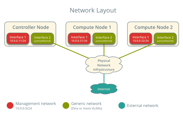
For illustration purposes, the management network uses 10.0.0.0/24 and provider networks use 192.0.2.0/24, 198.51.100.0/24, and 203.0.113.0/24.
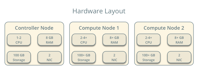
Infrastructure
- One controller node with two network interfaces: management and provider. The provider interface connects to a generic network that physical network infrastructure switches/routes to external networks (typically the Internet).
- At least two compute nodes with two network interfaces: management and provider. The provider interface connects to a generic network that physical network infrastructure switches/routes to external networks (typically the Internet).
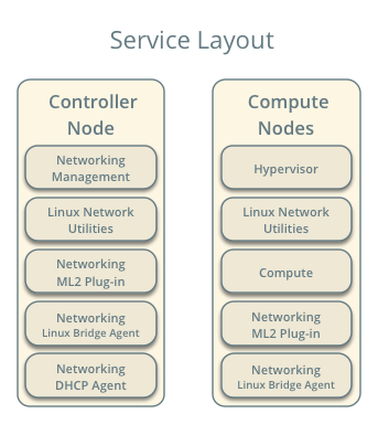
OpenStack services - controller node
- Operational SQL server with neutron database and appropriate configuration in the neutron.conf file.
- Operational message queue service with appropriate configuration in the neutron.conf file.
- Operational OpenStack Identity service with appropriate configuration in the neutron.conf file.
- Operational OpenStack Compute controller/management service with appropriate configuration to use neutron in the nova.conf file.
- Neutron server service, ML2 plug-in, Linux bridge agent, DHCP agent, and any dependencies.
OpenStack services - compute nodes
- Operational OpenStack Identity service with appropriate configuration in the neutron.conf file.
- Operational OpenStack Compute controller/management service with appropriate configuration to use neutron in the nova.conf file.
- ML2 plug-in, Linux bridge agent, and any dependencies.
Architecture
The general provider network architecture uses physical network infrastructure to handle switching and routing of network traffic.
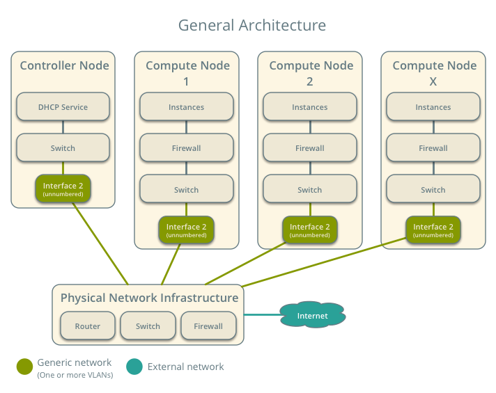
The controller node contains the following network components:
- Linux bridge agent managing virtual switches, connectivity among them, and interaction via virtual ports with other network components such as namespaces and underlying interfaces.
- DHCP agent managing the qdhcp namespaces. The qdhcp namespaces provide DHCP services for instances using provider networks.
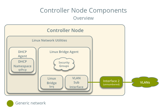
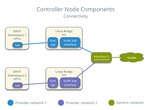
Note
For illustration purposes, the diagram contains two different provider networks.
The compute nodes contain the following network components:
- Linux bridge agent managing virtual switches, connectivity among them, and interaction via virtual ports with other network components such as namespaces, security groups, and underlying interfaces.
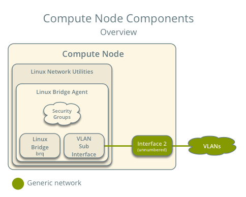
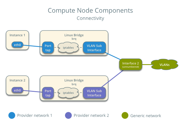
Note
For illustration purposes, the diagram contains two different provider networks.
Packet flow
Note
North-south network traffic travels between an instance and external network, typically the Internet. East-west network traffic travels between instances.
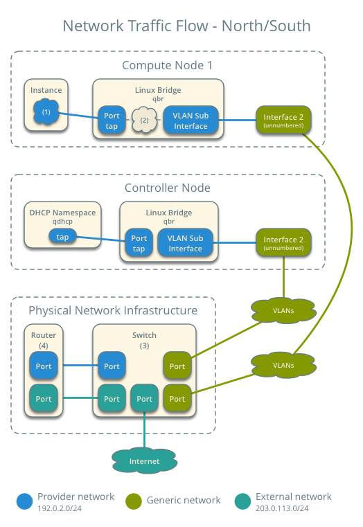
Case 1: North-south
The physical network infrastructure handles routing and potentially other services between the provider and external network. In this case, provider and external simply differentiate between a network available to instances and a network only accessible via router, respectively, to illustrate that the physical network infrastructure handles routing. However, provider networks support direct connection to external networks such as the Internet.
- External network
- Network 203.0.113.0/24
- Provider network (VLAN)
- Network 192.0.2.0/24
- Gateway 192.0.2.1 with MAC address TG
- Compute node 1
- Instance 1 192.0.2.11 with MAC address I1
- Instance 1 resides on compute node 1 and uses a provider network.
- The instance sends a packet to a host on the external network.
The following steps involve compute node 1.
- The instance 1 tap interface (1) forwards the packet to the provider bridge qbr. The packet contains destination MAC address TG because the destination resides on another network.
- Security group rules (2) on the provider bridge qbr handle firewalling and tracking for the packet.
- The provider bridge qbr forwards the packet to the logical VLAN interface device.sid where device references the underlying physical provider interface and sid contains the provider network segmentation ID.
- The logical VLAN interface device.sid forwards the packet to the physical network via the physical provider interface.
The following steps involve the physical network infrastructure:
- A switch (3) handles any VLAN tag operations between the provider network and the router (4).
- A router (4) routes the packet from the provider network to the external network.
- A switch (3) handles any VLAN tag operations between the router (4) and the external network.
- A switch (3) forwards the packet to the external network.
Note
Return traffic follows similar steps in reverse.
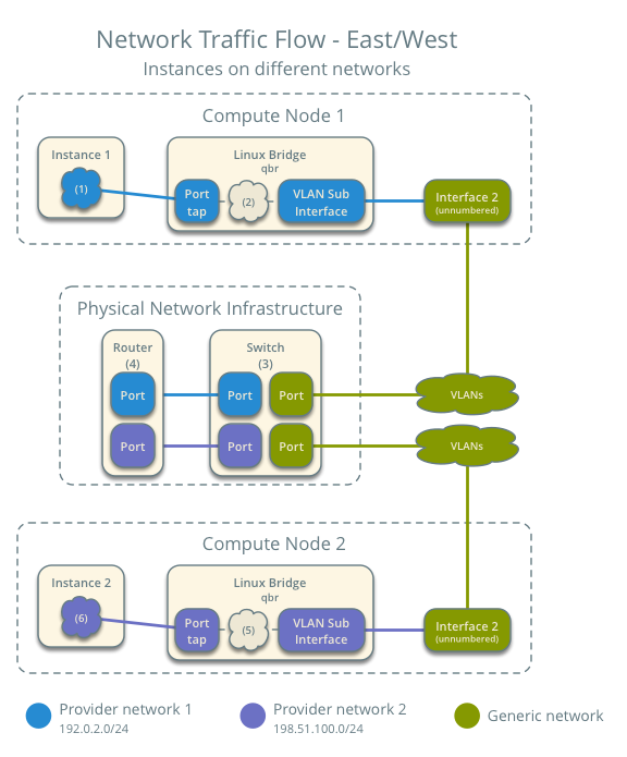
Case 2: East-west for instances on different networks
The physical network infrastructure handles routing between the provider networks.
- Provider network 1
- Network: 192.0.2.0/24
- Gateway: 192.0.2.1 with MAC address TG1
- Provider network 2
- Network: 198.51.100.0/24
- Gateway: 198.51.100.1 with MAC address TG2
- Compute node 1
- Instance 1: 192.0.2.11 with MAC address I1
- Compute node 2
- Instance 2: 198.51.100.11 with MAC address I2
- Instance 1 resides on compute node 1 and uses provider network 1.
- Instance 2 resides on compute node 2 and uses provider network 2.
- Instance 1 sends a packet to instance 2.
The following steps involve compute node 1:
- The instance 1 tap interface forwards the packet to the provider bridge qbr. The packet contains destination MAC address TG1 because the destination resides on another network.
- Security group rules on the provider bridge qbr handle firewalling and state tracking for the packet.
- The provider bridge qbr forwards the packet to the logical VLAN interface device.sid where device references the underlying physical provider interface and sid contains the provider network segmentation ID.
- The logical VLAN interface device.sid forwards the packet to the physical network infrastructure via the physical provider interface.
The following steps involve the physical network infrastructure:
- A switch (3) handles any VLAN tag operations between provider network 1 and the router (4).
- A router (4) routes the packet from provider network 1 to provider network 2.
- A switch (3) handles any VLAN tag operations between the router (4) and provider network 2.
- A switch (3) forwards the packet to compute node 2.
The following steps involve compute node 2:
- The physical provider interface forwards the packet to the logical VLAN interface device.sid where device references the underlying physical provider interface and sid contains the provider network segmentation ID.
- The logical VLAN interface device.sid forwards the packet to the provider bridge qbr.
- Security group rules (5) on the provider bridge qbr handle firewalling and state tracking for the packet.
- The provider bridge qbr forwards the packet to the tap interface (6) on instance 2.
Note
Return traffic follows similar steps in reverse.
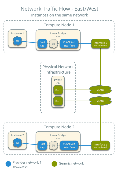
Case 3: East-west for instances on the same network
The physical network infrastructure handles switching within the provider network.
- Provider network
- Network: 192.0.2.0/24
- Compute node 1
- Instance 1: 192.0.2.11 with MAC address I1
- Compute node 2
- Instance 2: 192.0.2.12 with MAC address I2
- Instance 1 resides on compute node 1.
- Instance 2 resides on compute node 2.
- Both instances use the same provider network.
- Instance 1 sends a packet to instance 2.
The following steps involve compute node 1:
- The instance 1 tap interface (1) forwards the packet to the provider bridge qbr. The packet contains destination MAC address I2 because the destination resides on the same network.
- Security group rules (2) on the provider bridge qbr handle firewalling and state tracking for the packet.
- The provider bridge qbr forwards the packet to the logical VLAN interface device.sid where device references the underlying physical provider interface and sid contains the provider network segmentation ID.
- The logical VLAN interface device.sid forwards the packet to the physical network infrastructure via the physical provider interface.
The following steps involve the physical network infrastructure:
- A switch (3) forwards the packet from compute node 1 to compute node 2.
The following steps involve compute node 2:
- The physical provider interface forwards the packet to the logical VLAN interface device.sid where device references the underlying physical provider interface and sid contains the provider network segmentation ID.
- The logical VLAN interface device.sid forwards the packet to the provider bridge qbr.
- Security group rules (4) on the provider bridge qbr handle firewalling and state tracking for the packet.
- The provider bridge qbr forwards the packet to the instance 2 tap interface (5).
Note
Return traffic follows similar steps in reverse.
Example configuration
Use the following example configuration as a template to deploy this scenario in your environment.
Note
To further simplify this scenario, we recommend using a configuration drive rather than the conventional metadata agent to provide instance metadata.
Controller node
Configure common options. Edit the /etc/neutron/neutron.conf file:
[DEFAULT]
verbose = True
core_plugin = ml2
service_plugins =
Note
The service_plugins option contains no value because the Networking service does not provide layer-3 services such as routing. However, this breaks portions of the dashboard that manage the Networking service. See the Installation Guide for more information.
Configure the ML2 plug-in and Linux bridge agent. Edit the /etc/neutron/plugins/ml2/ml2_conf.ini file:
[ml2]
type_drivers = flat,vlan
tenant_network_types =
mechanism_drivers = linuxbridge
extension_drivers = port_security

[ml2_type_flat]
flat_networks = provider

[ml2_type_vlan]
network_vlan_ranges = provider

[securitygroup]
enable_ipset = True
Replace PROVIDER_INTERFACE with the name of the underlying interface that handles provider networks. For example, eth1.
Note
The tenant_network_types option contains no value because the architecture does not support project (private) networks.
Note
The provider value in the network_vlan_ranges option lacks VLAN ID ranges to support use of arbitrary VLAN IDs.
Configure the Linux bridge agent. Edit the /etc/neutron/plugins/ml2/linuxbridge_agent.ini file:
[linux_bridge]
physical_interface_mappings = provider:PROVIDER_INTERFACE

[vxlan]
enable_vxlan = False

[agent]
prevent_arp_spoofing = True

[securitygroup]
firewall_driver = neutron.agent.linux.iptables_firewall.IptablesFirewallDriver
enable_security_group = True
Configure the DHCP agent. Edit the /etc/neutron/dhcp_agent.ini file:
[DEFAULT]
verbose = True
interface_driver = neutron.agent.linux.interface.BridgeInterfaceDriver
dhcp_driver = neutron.agent.linux.dhcp.Dnsmasq
enable_isolated_metadata = True
Start the following services:
- Server
- Linux bridge agent
- DHCP agent
Compute nodes
Configure common options. Edit the /etc/neutron/neutron.conf file:
[DEFAULT]
verbose = True
Configure the Linux bridge agent. Edit the /etc/neutron/plugins/ml2/linuxbridge_agent.ini file:
[linux_bridge]
physical_interface_mappings = provider:PROVIDER_INTERFACE

[vxlan]
enable_vxlan = False

[agent]
prevent_arp_spoofing = True

[securitygroup]
firewall_driver = neutron.agent.linux.iptables_firewall.IptablesFirewallDriver
enable_security_group = True
Replace PROVIDER_INTERFACE with the name of the underlying interface that handles provider networks. For example, eth1.
Start the following services:
- Linux bridge agent
Verify service operation
Source the administrative project credentials.
Verify presence and operation of the agents:
$ neutron agent-list
+--------------------------------------+--------------------+------------+-------+----------------+---------------------------+
| id                                   | agent_type         | host       | alive | admin_state_up | binary                    |
+--------------------------------------+--------------------+------------+-------+----------------+---------------------------+
| 09de6af6-c5f1-4548-8b09-18801f068c57 | Linux bridge agent | compute2   | :-)   | True           | neutron-linuxbridge-agent |
| 188945d1-9e70-4803-a276-df924e0788a4 | Linux bridge agent | compute1   | :-)   | True           | neutron-linuxbridge-agent |
| e76c440d-d5f6-4316-a674-d689630b629e | DHCP agent         | controller | :-)   | True           | neutron-dhcp-agent        |
| e9901853-6687-45b1-8a92-3712bdec0416 | Linux bridge agent | controller | :-)   | True           | neutron-linuxbridge-agent |
+--------------------------------------+--------------------+------------+-------+----------------+---------------------------+
Create initial networks
This example creates a VLAN provider network. Change the VLAN ID and IP address range to values suitable for your environment.
Source the administrative project credentials.
Create a provider network:
$ neutron net-create provider-101 --shared \
  --provider:physical_network provider --provider:network_type vlan \
  --provider:segmentation_id 101
Created a new network:
+---------------------------+--------------------------------------+
| Field                     | Value                                |
+---------------------------+--------------------------------------+
| admin_state_up            | True                                 |
| id                        | 572a3fc9-ad1f-4e54-a63a-4bf5047c1a4a |
| name                      | provider-101                         |
| provider:network_type     | vlan                                 |
| provider:physical_network | provider                             |
| provider:segmentation_id  | 101                                  |
| router:external           | False                                |
| shared                    | True                                 |
| status                    | ACTIVE                               |
| subnets                   |                                      |
| tenant_id                 | e0bddbc9210d409795887175341b7098     |
+---------------------------+--------------------------------------+
Note
The shared option allows any project to use this network.
Create a subnet on the provider network:
$ neutron subnet-create provider-101 203.0.113.0/24 \
  --name provider-101-subnet --gateway 203.0.113.1
Created a new subnet:
+-------------------+--------------------------------------------------+
| Field             | Value                                            |
+-------------------+--------------------------------------------------+
| allocation_pools  | {"start": "203.0.113.2", "end": "203.0.113.254"} |
| cidr              | 203.0.113.0/24                                   |
| dns_nameservers   |                                                  |
| enable_dhcp       | True                                             |
| gateway_ip        | 203.0.113.1                                      |
| host_routes       |                                                  |
| id                | ff6c9a0b-0c81-4ce4-94e6-c6617a059bab             |
| ip_version        | 4                                                |
| ipv6_address_mode |                                                  |
| ipv6_ra_mode      |                                                  |
| name              | provider-101-subnet                              |
| network_id        | 572a3fc9-ad1f-4e54-a63a-4bf5047c1a4a             |
| tenant_id         | e0bddbc9210d409795887175341b7098                 |
+-------------------+--------------------------------------------------+
Verify network operation
On the controller node, verify creation of the qdhcp namespace:
$ ip netns
qdhcp-8b868082-e312-4110-8627-298109d4401c
Note
The qdhcp namespace might not exist until launching an instance.
Source the regular project credentials. The following steps use the demo project.
Create the appropriate security group rules to allow ping and SSH access to the instance. For example:
$ nova secgroup-add-rule default icmp -1 -1 0.0.0.0/0
+-------------+-----------+---------+-----------+--------------+
| IP Protocol | From Port | To Port | IP Range  | Source Group |
+-------------+-----------+---------+-----------+--------------+
| icmp        | -1        | -1      | 0.0.0.0/0 |              |
+-------------+-----------+---------+-----------+--------------+

$ nova secgroup-add-rule default tcp 22 22 0.0.0.0/0
+-------------+-----------+---------+-----------+--------------+
| IP Protocol | From Port | To Port | IP Range  | Source Group |
+-------------+-----------+---------+-----------+--------------+
| tcp         | 22        | 22      | 0.0.0.0/0 |              |
+-------------+-----------+---------+-----------+--------------+
Launch an instance with an interface on the provider network.
Note
This example uses a CirrOS image that was manually uploaded into the Image Service
$ nova boot --flavor m1.tiny --image cirros-0.3.3-x86_64-disk test_server
+--------------------------------------+-----------------------------------------------------------------+
| Property                             | Value                                                           |
+--------------------------------------+-----------------------------------------------------------------+
| OS-DCF:diskConfig                    | MANUAL                                                          |
| OS-EXT-AZ:availability_zone          | nova                                                            |
| OS-EXT-SRV-ATTR:host                 | -                                                               |
| OS-EXT-SRV-ATTR:hypervisor_hostname  | -                                                               |
| OS-EXT-SRV-ATTR:instance_name        | instance-00000001                                               |
| OS-EXT-STS:power_state               | 0                                                               |
| OS-EXT-STS:task_state                | scheduling                                                      |
| OS-EXT-STS:vm_state                  | building                                                        |
| OS-SRV-USG:launched_at               | -                                                               |
| OS-SRV-USG:terminated_at             | -                                                               |
| accessIPv4                           |                                                                 |
| accessIPv6                           |                                                                 |
| adminPass                            | h7CkMdkRXuuh                                                    |
| config_drive                         |                                                                 |
| created                              | 2015-07-22T20:40:16Z                                            |
| flavor                               | m1.tiny (1)                                                     |
| hostId                               |                                                                 |
| id                                   | dee2a9f4-e24c-444d-8c94-386f11f74af5                            |
| image                                | cirros-0.3.3-x86_64-disk (2b6bb38f-f69f-493c-a1c0-264dfd4188d8) |
| key_name                             | -                                                               |
| metadata                             | {}                                                              |
| name                                 | test_server                                                     |
| os-extended-volumes:volumes_attached | []                                                              |
| progress                             | 0                                                               |
| security_groups                      | default                                                         |
| status                               | BUILD                                                           |
| tenant_id                            | 5f2db133e98e4bc2999ac2850ce2acd1                                |
| updated                              | 2015-07-22T20:40:16Z                                            |
| user_id                              | ea417ebfa86741af86f84a5dbcc97cd2                                |
+--------------------------------------+-----------------------------------------------------------------+
Determine the IP address of the instance. The following step uses 203.0.113.3.
$ nova list
+--------------------------------------+-------------+--------+------------+-------------+--------------------------+
| ID                                   | Name        | Status | Task State | Power State | Networks                 |
+--------------------------------------+-------------+--------+------------+-------------+--------------------------+
| dee2a9f4-e24c-444d-8c94-386f11f74af5 | test_server | ACTIVE | -          | Running     | provider-101=203.0.113.3 |
+--------------------------------------+-------------+--------+------------+-------------+--------------------------+
On the controller node or any host with access to the provider network, ping the IP address of the instance:
$ ping -c 4 203.0.113.3
PING 203.0.113.3 (203.0.113.3) 56(84) bytes of data.
64 bytes from 203.0.113.3: icmp_req=1 ttl=63 time=3.18 ms
64 bytes from 203.0.113.3: icmp_req=2 ttl=63 time=0.981 ms
64 bytes from 203.0.113.3: icmp_req=3 ttl=63 time=1.06 ms
64 bytes from 203.0.113.3: icmp_req=4 ttl=63 time=0.929 ms

--- 203.0.113.3 ping statistics ---
4 packets transmitted, 4 received, 0% packet loss, time 3002ms
rtt min/avg/max/mdev = 0.929/1.539/3.183/0.951 ms
Obtain access to the instance.
Test connectivity to the Internet:
$ ping -c 4 openstack.org
PING openstack.org (174.143.194.225) 56(84) bytes of data.
64 bytes from 174.143.194.225: icmp_req=1 ttl=53 time=17.4 ms
64 bytes from 174.143.194.225: icmp_req=2 ttl=53 time=17.5 ms
64 bytes from 174.143.194.225: icmp_req=3 ttl=53 time=17.7 ms
64 bytes from 174.143.194.225: icmp_req=4 ttl=53 time=17.5 ms

--- openstack.org ping statistics ---
4 packets transmitted, 4 received, 0% packet loss, time 3003ms
rtt min/avg/max/mdev = 17.431/17.575/17.734/0.143 ms

Except where otherwise noted, this document is licensed under Creative Commons Attribution 3.0 License. See all OpenStack Legal Documents.