Open vSwitch: Provider networks
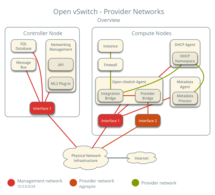
This architecture example provides layer-2 connectivity between instances and the physical network infrastructure using VLAN (802.1q) tagging. It supports one untagged (flat) network and up to 4095 tagged (VLAN) networks. The actual quantity of VLAN networks depends on the physical network infrastructure. For more information on provider networks, see Provider networks.
Warning
Linux distributions often package older releases of Open vSwitch that can introduce issues during operation with the Networking service. We recommend using at least the latest long-term stable (LTS) release of Open vSwitch for the best experience and support from Open vSwitch. See http://www.openvswitch.org for available releases and the installation instructions for
Prerequisites
One controller node with the following components:
- Two network interfaces: management and provider.
- OpenStack Networking server service and ML2 plug-in.
Two compute nodes with the following components:
- Two network interfaces: management and provider.
- OpenStack Networking Open vSwitch (OVS) layer-2 agent, DHCP agent, metadata agent, and any dependencies including OVS.
Note
Larger deployments typically deploy the DHCP and metadata agents on a subset of compute nodes to increase performance and redundancy. However, too many agents can overwhelm the message bus. Also, to further simplify any deployment, you can omit the metadata agent and use a configuration drive to provide metadata to instances.
Architecture
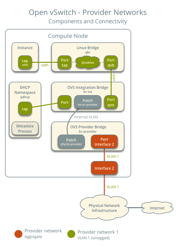
The following figure shows components and connectivity for one untagged (flat) network. In this particular case, the instance resides on the same compute node as the DHCP agent for the network. If the DHCP agent resides on another compute node, the latter only contains a DHCP namespace with a port on the OVS integration bridge.
The following figure describes virtual connectivity among components for two tagged (VLAN) networks. Essentially, all networks use a single OVS integration bridge with different internal VLAN tags. The internal VLAN tags almost always differ from the network VLAN assignment in the Networking service. Similar to the untagged network case, the DHCP agent may reside on a different compute node.
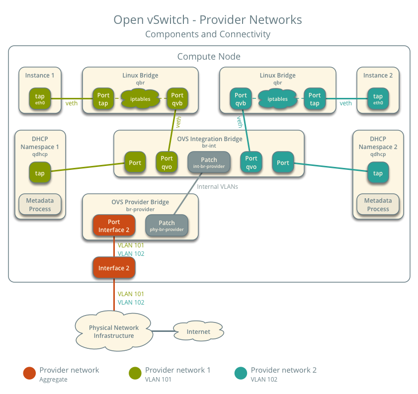
Note
These figures omit the controller node because it does not handle instance network traffic.
Example configuration
Use the following example configuration as a template to deploy provider networks in your environment.
Controller node
Install the Networking service components that provide the neutron-server service and ML2 plug-in.
In the neutron.conf file:
Configure common options:
[DEFAULT]
core_plugin = ml2
auth_strategy = keystone
rpc_backend = rabbit
notify_nova_on_port_status_changes = true
notify_nova_on_port_data_changes = true

[database]
...

[keystone_authtoken]
...

[oslo_messaging_rabbit]
...

[nova]
...
See the Installation Guide for your OpenStack release to obtain the appropriate configuration for the [database], [keystone_authtoken], [oslo_messaging_rabbit], and [nova] sections.
Disable service plug-ins because provider networks do not require any. However, this breaks portions of the dashboard that manage the Networking service. See the Installation Guide for more information.
[DEFAULT]
service_plugins =
Enable two DHCP agents per network so both compute nodes can provide DHCP service provider networks.
[DEFAULT]
dhcp_agents_per_network = 2
If necessary, configure MTU.
In the ml2_conf.ini file:
Configure drivers and network types:
[ml2]
type_drivers = flat,vlan
tenant_network_types =
mechanism_drivers = openvswitch
extension_drivers = port_security
Configure network mappings:
[ml2_type_flat]
flat_networks = provider

[ml2_type_vlan]
network_vlan_ranges = provider
Note
The tenant_network_types option contains no value because the architecture does not support self-service networks.
Note
The provider value in the network_vlan_ranges option lacks VLAN ID ranges to support use of arbitrary VLAN IDs.
Configure the security group driver:
[securitygroup]
firewall_driver = iptables_hybrid
Populate the database.
# su -s /bin/sh -c "neutron-db-manage --config-file /etc/neutron/neutron.conf \
  --config-file /etc/neutron/plugins/ml2/ml2_conf.ini upgrade head" neutron
Start the following services:
- Server
Compute nodes
Install the Networking service OVS layer-2 agent, DHCP agent, and metadata agent.
Install OVS.
In the neutron.conf file, configure common options:
[DEFAULT]
core_plugin = ml2
auth_strategy = keystone
rpc_backend = rabbit
notify_nova_on_port_status_changes = true
notify_nova_on_port_data_changes = true

[database]
...

[keystone_authtoken]
...

[oslo_messaging_rabbit]
...

[nova]
...
See the Installation Guide for your OpenStack release to obtain the appropriate configuration for the [database], [keystone_authtoken], [oslo_messaging_rabbit], and [nova] sections.
In the openvswitch_agent.ini file, configure the OVS agent:
[ovs]
bridge_mappings = provider:br-provider

[securitygroup]
firewall_driver = iptables_hybrid
In the dhcp_agent.ini file, configure the DHCP agent:
[DEFAULT]
interface_driver = openvswitch
enable_isolated_metadata = True
In the metadata_agent.ini file, configure the metadata agent:
[DEFAULT]
nova_metadata_ip = controller
metadata_proxy_shared_secret = METADATA_SECRET
The value of METADATA_SECRET must match the value of the same option in the [neutron] section of the nova.conf file.
Start the following services:
- OVS
Create the OVS provider bridge br-provider:
$ ovs-vsctl add-br br-providerAdd the provider network interface as a port on the OVS provider bridge br-provider:
$ ovs-vsctl add-port br-provider PROVIDER_INTERFACEReplace PROVIDER_INTERFACE with the name of the underlying interface that handles provider networks. For example, eth1.
Start the following services:
- OVS agent
- DHCP agent
- Metadata agent
Verify service operation
Source the administrative project credentials.
Verify presence and operation of the agents:
$ neutron agent-list
+--------------------------------------+--------------------+----------+-------------------+-------+----------------+---------------------------+
| id                                   | agent_type         | host     | availability_zone | alive | admin_state_up | binary                    |
+--------------------------------------+--------------------+----------+-------------------+-------+----------------+---------------------------+
| 1236bbcb-e0ba-48a9-80fc-81202ca4fa51 | Metadata agent     | compute2 |                   | :-)   | True           | neutron-metadata-agent    |
| 457d6898-b373-4bb3-b41f-59345dcfb5c5 | Open vSwitch agent | compute2 |                   | :-)   | True           | neutron-openvswitch-agent |
| 71f15e84-bc47-4c2a-b9fb-317840b2d753 | DHCP agent         | compute2 | nova              | :-)   | True           | neutron-dhcp-agent        |
| a6c69690-e7f7-4e56-9831-1282753e5007 | Metadata agent     | compute1 |                   | :-)   | True           | neutron-metadata-agent    |
| af11f22f-a9f4-404f-9fd8-cd7ad55c0f68 | DHCP agent         | compute1 | nova              | :-)   | True           | neutron-dhcp-agent        |
| bcfc977b-ec0e-4ba9-be62-9489b4b0e6f1 | Open vSwitch agent | compute1 |                   | :-)   | True           | neutron-openvswitch-agent |
+--------------------------------------+--------------------+----------+-------------------+-------+----------------+---------------------------+
Create initial networks
The configuration supports one flat or multiple VLAN provider networks. For simplicity, the following procedure creates one flat provider network.
Source the administrative project credentials.
Create a flat network.
$ neutron net-create --shared --provider:physical_network provider \
  --provider:network_type flat provider1
Created a new network:
+---------------------------+--------------------------------------+
| Field                     | Value                                |
+---------------------------+--------------------------------------+
| admin_state_up            | True                                 |
| availability_zone_hints   |                                      |
| availability_zones        |                                      |
| description               |                                      |
| id                        | 2b5ad13f-3859-4847-8db7-c695ab7dfce6 |
| ipv4_address_scope        |                                      |
| ipv6_address_scope        |                                      |
| mtu                       | 1500                                 |
| name                      | provider1                            |
| port_security_enabled     | True                                 |
| provider:network_type     | flat                                 |
| provider:physical_network | provider                             |
| provider:segmentation_id  |                                      |
| router:external           | False                                |
| shared                    | True                                 |
| status                    | ACTIVE                               |
| subnets                   |                                      |
| tags                      |                                      |
| tenant_id                 | de59fed9547a4628b781df0862c837cf     |
+---------------------------+--------------------------------------+
Note
The shared option allows any project to use this network.
Note
To create a VLAN network instead of a flat network, change --provider:network_type flat to --provider:network_type vlan and add --provider:segmentation_id with a value referencing the VLAN ID.
Create a IPv4 subnet on the provider network.
 $ neutron subnet-create --name provider1-v4 --ip-version 4 \
   --allocation-pool start=203.0.113.11,end=203.0.113.250 \
   --gateway 203.0.113.1 --dns-nameserver 8.8.4.4 provider1 \
   203.0.113.0/24
 Created a new subnet:
 +-------------------+---------------------------------------------------+
 | Field             | Value                                             |
 +-------------------+---------------------------------------------------+
 | allocation_pools  | {"start": "203.0.113.11", "end": "203.0.113.250"} |
 | cidr              | 203.0.113.0/24                                    |
 | description       |                                                   |
 | dns_nameservers   | 8.8.4.4                                           |
 | enable_dhcp       | True                                              |
 | gateway_ip        | 203.0.113.1                                       |
 | host_routes       |                                                   |
 | id                | 7ce3fd60-1d45-4432-a9a5-4f7645629bd9              |
 | ip_version        | 4                                                 |
 | ipv6_address_mode |                                                   |
 | ipv6_ra_mode      |                                                   |
 | name              | provider1-v4                                      |
| network_id        | 2b5ad13f-3859-4847-8db7-c695ab7dfce6              |
 | subnetpool_id     |                                                   |
 | tenant_id         | de59fed9547a4628b781df0862c837cf                  |
 +-------------------+---------------------------------------------------+
Create a IPv6 subnet on the provider network.
$ neutron subnet-create --name provider1-v6 --ip-version 6 \
  --gateway fd00:203:0:113::1 --dns-nameserver 2001:4860:4860::8844 \
  provider1 fd00:203:0:113::/64
Created a new subnet:
+-------------------+-----------------------------------------------------------------------------+
| Field             | Value                                                                       |
+-------------------+-----------------------------------------------------------------------------+
| allocation_pools  | {"start": "fd00:203:0:113::2", "end": "fd00:203:0:113:ffff:ffff:ffff:ffff"} |
| cidr              | fd00:203:0:113::/64                                                         |
| description       |                                                                             |
| dns_nameservers   | 2001:4860:4860::8844                                                        |
| enable_dhcp       | True                                                                        |
| gateway_ip        | fd00:203:0:113::1                                                           |
| host_routes       |                                                                             |
| id                | 773ea59c-e8c1-4254-baf3-27d5b2d42eb5                                        |
| ip_version        | 6                                                                           |
| ipv6_address_mode |                                                                             |
| ipv6_ra_mode      |                                                                             |
| name              | provider1-v6                                                                |
| network_id        | 2b5ad13f-3859-4847-8db7-c695ab7dfce6                                        |
| subnetpool_id     |                                                                             |
| tenant_id         | de59fed9547a4628b781df0862c837cf                                            |
+-------------------+-----------------------------------------------------------------------------+
Note
By default, IPv6 provider networks rely on physical network infrastructure for stateless address autoconfiguration (SLAAC) and router advertisement.
Verify network operation
On each compute node, verify creation of the qdhcp namespace.
# ip netns
qdhcp-8b868082-e312-4110-8627-298109d4401c
Source a regular (non-administrative) project credentials.
Create the appropriate security group rules to allow ping and SSH access instances using the network.
$ openstack security group rule create --proto icmp default
+-----------------------+--------------------------------------+
| Field                 | Value                                |
+-----------------------+--------------------------------------+
| id                    | 2b45fbf8-45db-486c-915f-3f254740ae76 |
| ip_protocol           | icmp                                 |
| ip_range              | 0.0.0.0/0                            |
| parent_group_id       | d35188d0-6b10-4fb9-a6b9-891ed3feeb54 |
| port_range            |                                      |
| remote_security_group |                                      |
+-----------------------+--------------------------------------+

$ openstack security group rule create --proto ipv6-icmp default
+-----------------------+--------------------------------------+
| Field                 | Value                                |
+-----------------------+--------------------------------------+
| id                    | 2b45fbf8-45db-486c-915f-3f254740ae76 |
| ip_protocol           | ipv6-icmp                            |
| ip_range              | ::/0                                 |
| parent_group_id       | d35188d0-6b10-4fb9-a6b9-891ed3feeb54 |
| port_range            |                                      |
| remote_security_group |                                      |
+-----------------------+--------------------------------------+

$ openstack security group rule create --proto tcp --dst-port 22 default
+-----------------------+--------------------------------------+
| Field                 | Value                                |
+-----------------------+--------------------------------------+
| id                    | 86e5cc55-bb08-447a-a807-d36e2b9f56af |
| ip_protocol           | tcp                                  |
| ip_range              | 0.0.0.0/0                            |
| parent_group_id       | d35188d0-6b10-4fb9-a6b9-891ed3feeb54 |
| port_range            | 22:22                                |
| remote_security_group |                                      |
+-----------------------+--------------------------------------+
Launch an instance with an interface on the provider network. For example, a CirrOS image using flavor ID 1.
$ openstack server create --flavor 1 --image cirros \
  --nic net-id=NETWORK_ID provider-instance1
Replace NETWORK_ID with the ID of the provider network.
Determine the IPv4 and IPv6 addresses of the instance.
$ openstack server list
+--------------------------------------+--------------------+--------+--------------------------------------------+
| ID                                   | Name               | Status | Networks                                   |
+--------------------------------------+--------------------+--------+--------------------------------------------+
| 018e0ae2-b43c-4271-a78d-62653dd03285 | provider-instance1 | ACTIVE | provider1=203.0.113.13, fd00:203:0:113::13 |
+--------------------------------------+--------------------+--------+--------------------------------------------+
Note
The IPv4 and IPv6 addresses appear similar only for illustration purposes.
On the controller node or any host with access to the provider network, ping the IPv4 and IPv6 addresses of the instance.
$ ping -c 4 203.0.113.13
PING 203.0.113.13 (203.0.113.13) 56(84) bytes of data.
64 bytes from 203.0.113.13: icmp_req=1 ttl=63 time=3.18 ms
64 bytes from 203.0.113.13: icmp_req=2 ttl=63 time=0.981 ms
64 bytes from 203.0.113.13: icmp_req=3 ttl=63 time=1.06 ms
64 bytes from 203.0.113.13: icmp_req=4 ttl=63 time=0.929 ms

--- 203.0.113.13 ping statistics ---
4 packets transmitted, 4 received, 0% packet loss, time 3002ms
rtt min/avg/max/mdev = 0.929/1.539/3.183/0.951 ms

$ ping6 -c 4 fd00:203:0:113::13
PING fd00:203:0:113::13(fd00:203:0:113::13) 56 data bytes
64 bytes from fd00:203:0:113::13: icmp_seq=1 ttl=64 time=1.25 ms
64 bytes from fd00:203:0:113::13: icmp_seq=2 ttl=64 time=0.683 ms
64 bytes from fd00:203:0:113::13: icmp_seq=3 ttl=64 time=0.762 ms
64 bytes from fd00:203:0:113::13: icmp_seq=4 ttl=64 time=0.486 ms

--- fd00:203:0:113::13 ping statistics ---
4 packets transmitted, 4 received, 0% packet loss, time 2999ms
rtt min/avg/max/mdev = 0.486/0.796/1.253/0.282 ms
Obtain access to the instance.
Test IPv4 and IPv6 connectivity to the Internet or other external network.
Network traffic flow
The following sections describe the flow of network traffic in several common scenarios. North-south network traffic travels between an instance and external network such as the Internet. East-west network traffic travels between instances on the same or different networks. In all scenarios, the physical network infrastructure handles switching and routing among provider networks and external networks such as the Internet. Each case references one or more of the following components:
- Provider network 1 (VLAN)
- VLAN ID 101 (tagged)
- IP address ranges 203.0.113.0/24 and fd00:203:0:113::/64
- Gateway (via physical network infrastructure)
- IP addresses 203.0.113.1 and fd00:203:0:113:0::1
- Provider network 2 (VLAN)
- VLAN ID 102 (tagged)
- IP address range 192.0.2.0/24 and fd00:192:0:2::/64
- Gateway
- IP addresses 192.0.2.1 and fd00:192:0:2::1
- Instance 1
- IP addresses 203.0.113.101 and fd00:203:0:113:0::101
- Instance 2
- IP addresses 192.0.2.101 and fd00:192:0:2:0::101
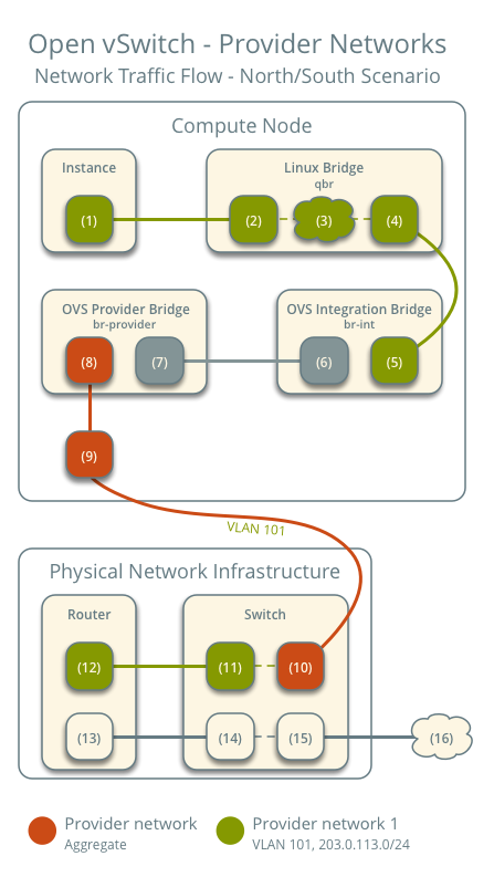
North-south
- The instance resides on compute node 1 and uses provider network 1.
- The instance sends a packet to a host on the Internet.
The following steps involve compute node 1.
- The instance interface (1) forwards the packet to the security group bridge instance port (2) via veth pair.
- Security group rules (3) on the security group bridge handle firewalling and connection tracking for the packet.
- The security group bridge OVS port (4) forwards the packet to the OVS integration bridge security group port (5) via veth pair.
- The OVS integration bridge adds an internal VLAN tag to the packet.
- The OVS integration bridge int-br-provider patch port (6) forwards the packet to the OVS provider bridge phy-br-provider patch port (7).
- The OVS provider bridge swaps the internal VLAN tag with actual VLAN tag 101.
- The OVS provider bridge provider network port (8) forwards the packet to the physical network interface (9).
- The physical network interface forwards the packet to the physical network infrastructure switch (10).
The following steps involve the physical network infrastructure:
- The switch removes VLAN tag 101 from the packet and forwards it to the router (11).
- The router routes the packet from the provider network (12) to the external network (13) and forwards the packet to the switch (14).
- The switch forwards the packet to the external network (15).
- The external network (16) receives the packet.
Note
Return traffic follows similar steps in reverse.
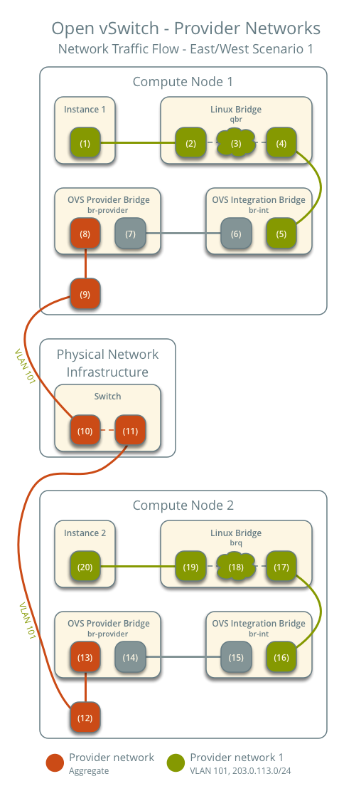
East-west scenario 1: Instances on the same network
Instances on the same network communicate directly between compute nodes containing those instances.
- Instance 1 resides on compute node 1 and uses provider network 1.
- Instance 2 resides on compute node 2 and uses provider network 1.
- Instance 1 sends a packet to instance 2.
The following steps involve compute node 1:
- The instance 1 interface (1) forwards the packet to the security group bridge instance port (2) via veth pair.
- Security group rules (3) on the security group bridge handle firewalling and connection tracking for the packet.
- The security group bridge OVS port (4) forwards the packet to the OVS integration bridge security group port (5) via veth pair.
- The OVS integration bridge adds an internal VLAN tag to the packet.
- The OVS integration bridge int-br-provider patch port (6) forwards the packet to the OVS provider bridge phy-br-provider patch port (7).
- The OVS provider bridge swaps the internal VLAN tag with actual VLAN tag 101.
- The OVS provider bridge provider network port (8) forwards the packet to the physical network interface (9).
- The physical network interface forwards the packet to the physical network infrastructure switch (10).
The following steps involve the physical network infrastructure:
- The switch forwards the packet from compute node 1 to compute node 2 (11).
The following steps involve compute node 2:
- The physical network interface (12) forwards the packet to the OVS provider bridge provider network port (13).
- The OVS provider bridge phy-br-provider patch port (14) forwards the packet to the OVS integration bridge int-br-provider patch port (15).
- The OVS integration bridge swaps the actual VLAN tag 101 with the internal VLAN tag.
- The OVS integration bridge security group port (16) forwards the packet to the security group bridge OVS port (17).
- Security group rules (18) on the security group bridge handle firewalling and connection tracking for the packet.
- The security group bridge instance port (19) forwards the packet to the instance 2 interface (20) via veth pair.
Note
Return traffic follows similar steps in reverse.
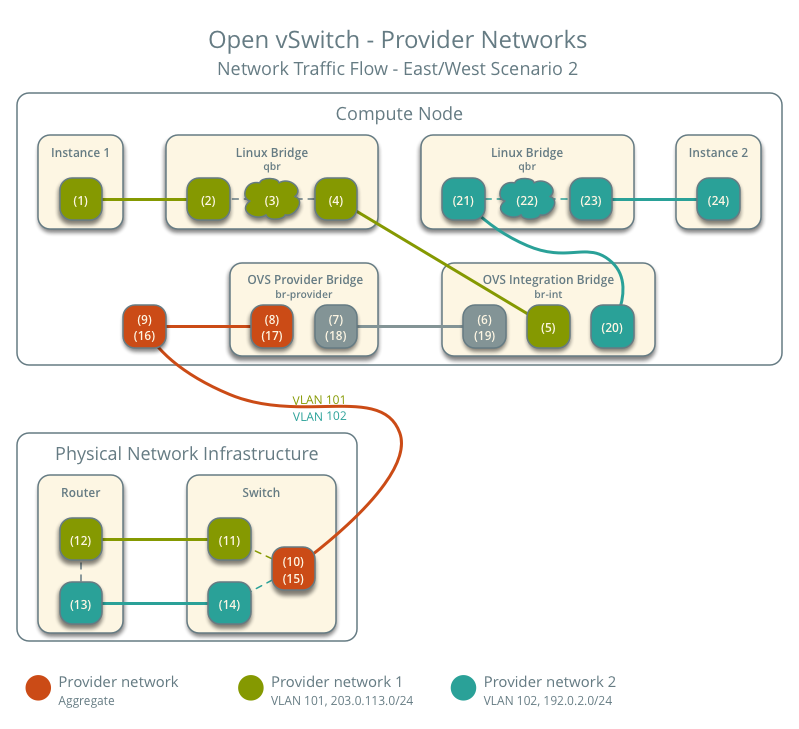
East-west scenario 2: Instances on different networks
Instances communicate via router on the physical network infrastructure.
- Instance 1 resides on compute node 1 and uses provider network 1.
- Instance 2 resides on compute node 1 and uses provider network 2.
- Instance 1 sends a packet to instance 2.
Note
Both instances reside on the same compute node to illustrate how VLAN tagging enables multiple logical layer-2 networks to use the same physical layer-2 network.
The following steps involve the compute node:
- The instance 1 interface (1) forwards the packet to the security group bridge instance port (2) via veth pair.
- Security group rules (3) on the security group bridge handle firewalling and connection tracking for the packet.
- The security group bridge OVS port (4) forwards the packet to the OVS integration bridge security group port (5) via veth pair.
- The OVS integration bridge adds an internal VLAN tag to the packet.
- The OVS integration bridge int-br-provider patch port (6) forwards the packet to the OVS provider bridge phy-br-provider patch port (7).
- The OVS provider bridge swaps the internal VLAN tag with actual VLAN tag 101.
- The OVS provider bridge provider network port (8) forwards the packet to the physical network interface (9).
- The physical network interface forwards the packet to the physical network infrastructure switch (10).
The following steps involve the physical network infrastructure:
- The switch removes VLAN tag 101 from the packet and forwards it to the router (11).
- The router routes the packet from provider network 1 (12) to provider network 2 (13).
- The router forwards the packet to the switch (14).
- The switch adds VLAN tag 102 to the packet and forwards it to compute node 1 (15).
The following steps involve the compute node:
- The physical network interface (16) forwards the packet to the OVS provider bridge provider network port (17).
- The OVS provider bridge phy-br-provider patch port (18) forwards the packet to the OVS integration bridge int-br-provider patch port (19).
- The OVS integration bridge swaps the actual VLAN tag 102 with the internal VLAN tag.
- The OVS integration bridge security group port (20) removes the internal VLAN tag and forwards the packet to the security group bridge OVS port (21).
- Security group rules (22) on the security group bridge handle firewalling and connection tracking for the packet.
- The security group bridge instance port (23) forwards the packet to the instance 2 interface (24) via veth pair.
Note
Return traffic follows similar steps in reverse.

Except where otherwise noted, this document is licensed under Creative Commons Attribution 3.0 License. See all OpenStack Legal Documents.