Open vSwitch: High availability using DVR
This architecture example augments the self-service deployment example with the Distributed Virtual Router (DVR) high-availability mechanism that provides connectivity between self-service and provider networks on compute nodes rather than network nodes for specific scenarios. For instances with a floating IPv4 address, routing between self-service and provider networks resides completely on the compute nodes to eliminate single point of failure and performance issues with network nodes. Routing also resides completely on the compute nodes for instances with a fixed or floating IPv4 address using self-service networks on the same distributed virtual router. However, instances with a fixed IP address still rely on the network node for routing and SNAT services between self-service and provider networks.
Consider the following attributes of this high-availability mechanism to determine practicality in your environment:
Only provides connectivity to an instance via the compute node on which the instance resides if the instance resides on a self-service network with a floating IPv4 address. Instances on self-service networks with only an IPv6 address or both IPv4 and IPv6 addresses rely on the network node for IPv6 connectivity.
The instance of a router on each compute node consumes an IPv4 address on the provider network on which it contains a gateway.
Prerequisites
Modify the compute nodes with the following components:
Install the OpenStack Networking layer-3 agent.
Note
Consider adding at least one additional network node to provide high-availability for instances with a fixed IP address. See See Distributed Virtual Routing with VRRP for more information.
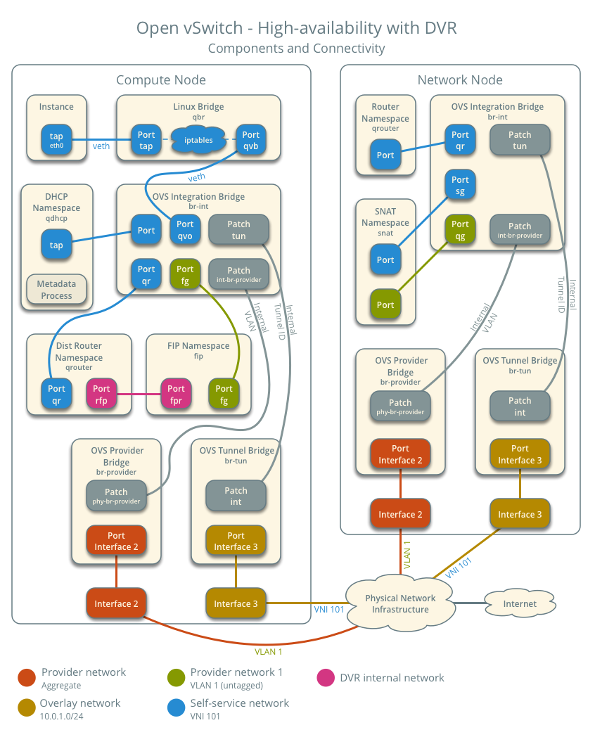
Architecture
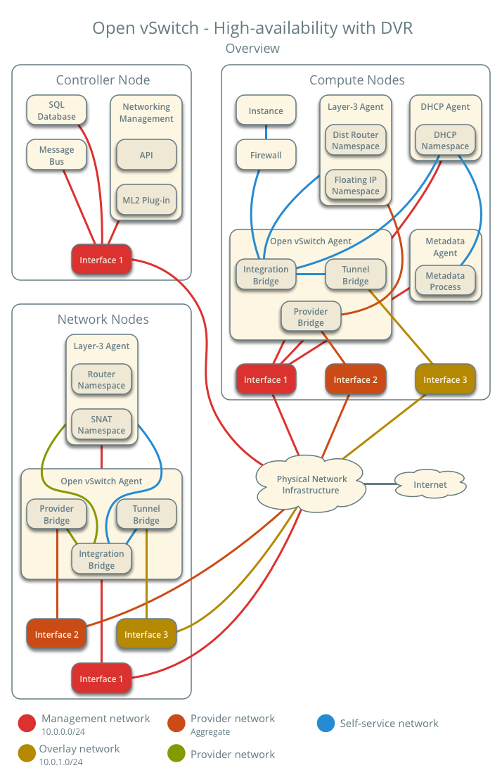
The following figure shows components and connectivity for one self-service network and one untagged (flat) network. In this particular case, the instance resides on the same compute node as the DHCP agent for the network. If the DHCP agent resides on another compute node, the latter only contains a DHCP namespace with a port on the OVS integration bridge.
Example configuration
Use the following example configuration as a template to add support for high-availability using DVR to an existing operational environment that supports self-service networks.
Controller node
In the
neutron.conffile:Enable distributed routing by default for all routers.
[DEFAULT]
router_distributed = True
Note
For a large scale cloud, if your deployment is running DVR with DHCP,
we recommend you set host_dvr_for_dhcp=False to achieve higher
L3 agent router processing performance. When this is set to False,
DNS functionality will not be available via the DHCP namespace (dnsmasq)
however, a different nameserver will have to be configured, for
example, by specifying a value in dns_nameservers for subnets.
Restart the following services:
Server
Network node
In the
openvswitch_agent.inifile, enable distributed routing.[agent] enable_distributed_routing = True
In the
l3_agent.inifile, configure the layer-3 agent to provide SNAT services.[DEFAULT] agent_mode = dvr_snat
Restart the following services:
Open vSwitch agent
Layer-3 agent
Compute nodes
Install the Networking service layer-3 agent.
In the
openswitch_agent.inifile, enable distributed routing.[agent] enable_distributed_routing = True
In the
l3_agent.inifile, configure the layer-3 agent.[DEFAULT] interface_driver = openvswitch agent_mode = dvr
Restart the following services:
Open vSwitch agent
Layer-3 agent
Verify service operation
Source the administrative project credentials.
Verify presence and operation of the agents.
$ openstack network agent list
+--------------------------------------+--------------------+----------+-------------------+-------+-------+---------------------------+
| ID                                   | Agent Type         | Host     | Availability Zone | Alive | State | Binary                    |
+--------------------------------------+--------------------+----------+-------------------+-------+-------+---------------------------+
| 05d980f2-a4fc-4815-91e7-a7f7e118c0db | L3 agent           | compute1 | nova              | True  | UP    | neutron-l3-agent          |
| 1236bbcb-e0ba-48a9-80fc-81202ca4fa51 | Metadata agent     | compute2 | None              | True  | UP    | neutron-metadata-agent    |
| 2a2e9a90-51b8-4163-a7d6-3e199ba2374b | L3 agent           | compute2 | nova              | True  | UP    | neutron-l3-agent          |
| 457d6898-b373-4bb3-b41f-59345dcfb5c5 | Open vSwitch agent | compute2 | None              | True  | UP    | neutron-openvswitch-agent |
| 513caa68-0391-4e53-a530-082e2c23e819 | Linux bridge agent | compute1 | None              | True  | UP    | neutron-linuxbridge-agent |
| 71f15e84-bc47-4c2a-b9fb-317840b2d753 | DHCP agent         | compute2 | nova              | True  | UP    | neutron-dhcp-agent        |
| 8805b962-de95-4e40-bdc2-7a0add7521e8 | L3 agent           | network1 | nova              | True  | UP    | neutron-l3-agent          |
| a33cac5a-0266-48f6-9cac-4cef4f8b0358 | Open vSwitch agent | network1 | None              | True  | UP    | neutron-openvswitch-agent |
| a6c69690-e7f7-4e56-9831-1282753e5007 | Metadata agent     | compute1 | None              | True  | UP    | neutron-metadata-agent    |
| af11f22f-a9f4-404f-9fd8-cd7ad55c0f68 | DHCP agent         | compute1 | nova              | True  | UP    | neutron-dhcp-agent        |
| bcfc977b-ec0e-4ba9-be62-9489b4b0e6f1 | Open vSwitch agent | compute1 | None              | True  | UP    | neutron-openvswitch-agent |
+--------------------------------------+--------------------+----------+-------------------+-------+-------+---------------------------+
Create initial networks
Similar to the self-service deployment example, this configuration supports multiple VXLAN self-service networks. After enabling high-availability, all additional routers use distributed routing. The following procedure creates an additional self-service network and router. The Networking service also supports adding distributed routing to existing routers.
Source a regular (non-administrative) project credentials.
Create a self-service network.
$ openstack network create selfservice2
+-------------------------+--------------+
| Field                   | Value        |
+-------------------------+--------------+
| admin_state_up          | UP           |
| mtu                     | 1450         |
| name                    | selfservice2 |
| port_security_enabled   | True         |
| revision_number         | 1            |
| router:external         | Internal     |
| shared                  | False        |
| status                  | ACTIVE       |
| tags                    | []           |
+-------------------------+--------------+
Create a IPv4 subnet on the self-service network.
$ openstack subnet create --subnet-range 192.0.2.0/24 \
  --network selfservice2 --dns-nameserver 8.8.4.4 selfservice2-v4
+-------------------+---------------------------+
| Field             | Value                     |
+-------------------+---------------------------+
| allocation_pools  | 192.0.2.2-192.0.2.254     |
| cidr              | 192.0.2.0/24              |
| dns_nameservers   | 8.8.4.4                   |
| enable_dhcp       | True                      |
| gateway_ip        | 192.0.2.1                 |
| ip_version        | 4                         |
| name              | selfservice2-v4           |
| revision_number   | 1                         |
| tags              | []                        |
+-------------------+---------------------------+
Create a IPv6 subnet on the self-service network.
$ openstack subnet create --subnet-range fd00:192:0:2::/64 --ip-version 6 \
  --ipv6-ra-mode slaac --ipv6-address-mode slaac --network selfservice2 \
  --dns-nameserver 2001:4860:4860::8844 selfservice2-v6
+-------------------+------------------------------------------------------+
| Field             | Value                                                |
+-------------------+------------------------------------------------------+
| allocation_pools  | fd00:192:0:2::2-fd00:192:0:2:ffff:ffff:ffff:ffff     |
| cidr              | fd00:192:0:2::/64                                    |
| dns_nameservers   | 2001:4860:4860::8844                                 |
| enable_dhcp       | True                                                 |
| gateway_ip        | fd00:192:0:2::1                                      |
| ip_version        | 6                                                    |
| ipv6_address_mode | slaac                                                |
| ipv6_ra_mode      | slaac                                                |
| name              | selfservice2-v6                                      |
| revision_number   | 1                                                    |
| tags              | []                                                   |
+-------------------+------------------------------------------------------+
Create a router.
$ openstack router create router2
+-----------------------+---------+
| Field                 | Value   |
+-----------------------+---------+
| admin_state_up        | UP      |
| name                  | router2 |
| revision_number       | 1       |
| status                | ACTIVE  |
| tags                  | []      |
+-----------------------+---------+
Add the IPv4 and IPv6 subnets as interfaces on the router.
$ openstack router add subnet router2 selfservice2-v4
$ openstack router add subnet router2 selfservice2-v6
Note
These commands provide no output.
Add the provider network as a gateway on the router.
$ openstack router set router2 --external-gateway provider1
Verify network operation
Source the administrative project credentials.
Verify distributed routing on the router.
$ openstack router show router2
+-------------------------+---------+
| Field                   | Value   |
+-------------------------+---------+
| admin_state_up          | UP      |
| distributed             | True    |
| ha                      | False   |
| name                    | router2 |
| revision_number         | 1       |
| status                  | ACTIVE  |
+-------------------------+---------+
On each compute node, verify creation of a
qrouternamespace with the same ID.Compute node 1:
# ip netns
qrouter-78d2f628-137c-4f26-a257-25fc20f203c1
Compute node 2:
# ip netns
qrouter-78d2f628-137c-4f26-a257-25fc20f203c1
On the network node, verify creation of the
snatandqrouternamespaces with the same ID.# ip netns snat-78d2f628-137c-4f26-a257-25fc20f203c1 qrouter-78d2f628-137c-4f26-a257-25fc20f203c1
Note
The namespace for router 1 from Open vSwitch: Self-service networks should also appear on network node 1 because of creation prior to enabling distributed routing.
Launch an instance with an interface on the additional self-service network. For example, a CirrOS image using flavor ID 1.
$ openstack server create --flavor 1 --image cirros --nic net-id=NETWORK_ID selfservice-instance2
Replace
NETWORK_IDwith the ID of the additional self-service network.Determine the IPv4 and IPv6 addresses of the instance.
$ openstack server list
+--------------------------------------+-----------------------+--------+----------------------------------------------------------+--------+---------+
| ID                                   | Name                  | Status | Networks                                                 | Image  | Flavor  |
+--------------------------------------+-----------------------+--------+----------------------------------------------------------+--------+---------+
| bde64b00-77ae-41b9-b19a-cd8e378d9f8b | selfservice-instance2 | ACTIVE | selfservice2=fd00:192:0:2:f816:3eff:fe71:e93e, 192.0.2.4 | cirros | m1.tiny |
+--------------------------------------+-----------------------+--------+----------------------------------------------------------+--------+---------+
Create a floating IPv4 address on the provider network.
$ openstack floating ip create provider1
+-------------------+--------------------------------------+
| Field             | Value                                |
+-------------------+--------------------------------------+
| fixed_ip          | None                                 |
| id                | 0174056a-fa56-4403-b1ea-b5151a31191f |
| instance_id       | None                                 |
| ip                | 203.0.113.17                         |
| pool              | provider1                            |
| revision_number   | 1                                    |
| tags              | []                                   |
+-------------------+--------------------------------------+
Associate the floating IPv4 address with the instance.
$ openstack server add floating ip selfservice-instance2 203.0.113.17
Note
This command provides no output.
On the compute node containing the instance, verify creation of the
fipnamespace with the same ID as the provider network.# ip netns fip-4bfa3075-b4b2-4f7d-b88e-df1113942d43
Network traffic flow
The following sections describe the flow of network traffic in several common scenarios. North-south network traffic travels between an instance and external network such as the Internet. East-west network traffic travels between instances on the same or different networks. In all scenarios, the physical network infrastructure handles switching and routing among provider networks and external networks such as the Internet. Each case references one or more of the following components:
Provider network (VLAN)
VLAN ID 101 (tagged)
Self-service network 1 (VXLAN)
VXLAN ID (VNI) 101
Self-service network 2 (VXLAN)
VXLAN ID (VNI) 102
Self-service router
Gateway on the provider network
Interface on self-service network 1
Interface on self-service network 2
Instance 1
Instance 2
This section only contains flow scenarios that benefit from distributed virtual routing or that differ from conventional operation. For other flow scenarios, see Network traffic flow.
North-south scenario 1: Instance with a fixed IP address
Similar to North-south scenario 1: Instance with a fixed IP address, except the router namespace on the network node becomes the SNAT namespace. The network node still contains the router namespace, but it serves no purpose in this case.
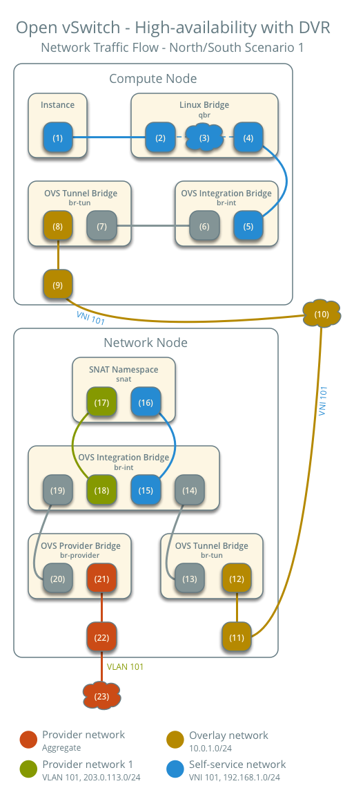
North-south scenario 2: Instance with a floating IPv4 address
For instances with a floating IPv4 address using a self-service network on a distributed router, the compute node containing the instance performs SNAT on north-south traffic passing from the instance to external networks such as the Internet and DNAT on north-south traffic passing from external networks to the instance. Floating IP addresses and NAT do not apply to IPv6. Thus, the network node routes IPv6 traffic in this scenario. north-south traffic passing between the instance and external networks such as the Internet.
Instance 1 resides on compute node 1 and uses self-service network 1.
A host on the Internet sends a packet to the instance.
The following steps involve the compute node:
The physical network infrastructure (1) forwards the packet to the provider physical network interface (2).
The provider physical network interface forwards the packet to the OVS provider bridge provider network port (3).
The OVS provider bridge swaps actual VLAN tag 101 with the internal VLAN tag.
The OVS provider bridge
phy-br-providerport (4) forwards the packet to the OVS integration bridgeint-br-providerport (5).The OVS integration bridge port for the provider network (6) removes the internal VLAN tag and forwards the packet to the provider network interface (7) in the floating IP namespace. This interface responds to any ARP requests for the instance floating IPv4 address.
The floating IP namespace routes the packet (8) to the distributed router namespace (9) using a pair of IP addresses on the DVR internal network. This namespace contains the instance floating IPv4 address.
The router performs DNAT on the packet which changes the destination IP address to the instance IP address on the self-service network via the self-service network interface (10).
The router forwards the packet to the OVS integration bridge port for the self-service network (11).
The OVS integration bridge adds an internal VLAN tag to the packet.
The OVS integration bridge removes the internal VLAN tag from the packet.
The OVS integration bridge security group port (12) forwards the packet to the security group bridge OVS port (13) via
vethpair.Security group rules (14) on the security group bridge handle firewalling and connection tracking for the packet.
The security group bridge instance port (15) forwards the packet to the instance interface (16) via
vethpair.
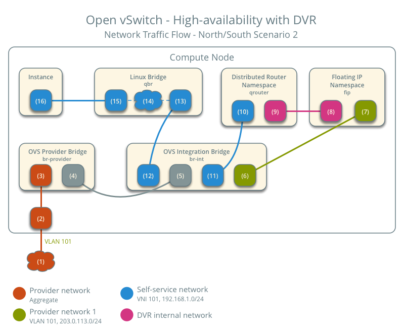
Note
Egress traffic follows similar steps in reverse, except SNAT changes the source IPv4 address of the packet to the floating IPv4 address.
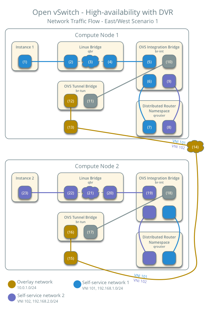
East-west scenario 1: Instances on different networks on the same router
Instances with fixed IPv4/IPv6 address or floating IPv4 address on the same compute node communicate via router on the compute node. Instances on different compute nodes communicate via an instance of the router on each compute node.
Note
This scenario places the instances on different compute nodes to show the most complex situation.
The following steps involve compute node 1:
The instance interface (1) forwards the packet to the security group bridge instance port (2) via
vethpair.Security group rules (3) on the security group bridge handle firewalling and connection tracking for the packet.
The security group bridge OVS port (4) forwards the packet to the OVS integration bridge security group port (5) via
vethpair.The OVS integration bridge adds an internal VLAN tag to the packet.
The OVS integration bridge port for self-service network 1 (6) removes the internal VLAN tag and forwards the packet to the self-service network 1 interface in the distributed router namespace (6).
The distributed router namespace routes the packet to self-service network 2.
The self-service network 2 interface in the distributed router namespace (8) forwards the packet to the OVS integration bridge port for self-service network 2 (9).
The OVS integration bridge adds an internal VLAN tag to the packet.
The OVS integration bridge exchanges the internal VLAN tag for an internal tunnel ID.
The OVS integration bridge
patch-tunport (10) forwards the packet to the OVS tunnel bridgepatch-intport (11).The OVS tunnel bridge (12) wraps the packet using VNI 101.
The underlying physical interface (13) for overlay networks forwards the packet to compute node 2 via the overlay network (14).
The following steps involve compute node 2:
The underlying physical interface (15) for overlay networks forwards the packet to the OVS tunnel bridge (16).
The OVS tunnel bridge unwraps the packet and adds an internal tunnel ID to it.
The OVS tunnel bridge exchanges the internal tunnel ID for an internal VLAN tag.
The OVS tunnel bridge
patch-intpatch port (17) forwards the packet to the OVS integration bridgepatch-tunpatch port (18).The OVS integration bridge removes the internal VLAN tag from the packet.
The OVS integration bridge security group port (19) forwards the packet to the security group bridge OVS port (20) via
vethpair.Security group rules (21) on the security group bridge handle firewalling and connection tracking for the packet.
The security group bridge instance port (22) forwards the packet to the instance 2 interface (23) via
vethpair.
Note
Routing between self-service networks occurs on the compute node containing the instance sending the packet. In this scenario, routing occurs on compute node 1 for packets from instance 1 to instance 2 and on compute node 2 for packets from instance 2 to instance 1.