Linux bridge: セルフサービスネットワーク
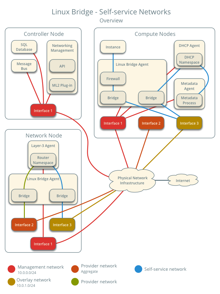
This architecture example augments Linux bridge: プロバイダーネットワーク to support a nearly limitless quantity of entirely virtual networks. Although the Networking service supports VLAN self-service networks, this example focuses on VXLAN self-service networks. For more information on self-service networks, see セルフサービスネットワーク.
注釈
The Linux bridge agent lacks support for other overlay protocols such as GRE and Geneve.
前提
Add one network node with the following components:
- Three network interfaces: management, provider, and overlay.
- OpenStack Networking Linux bridge layer-2 agent, layer-3 agent, and any
依存サービス。
Modify the compute nodes with the following components:
- Add one network interface: overlay.
注釈
You can keep the DHCP and metadata agents on each compute node or move them to the network node.
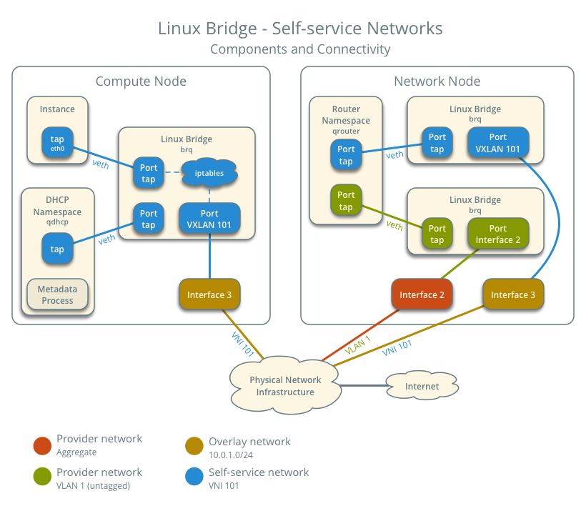
アーキテクチャー
The following figure shows components and connectivity for one self-service network and one untagged (flat) provider network. In this particular case, the instance resides on the same compute node as the DHCP agent for the network. If the DHCP agent resides on another compute node, the latter only contains a DHCP namespace and Linux bridge with a port on the overlay physical network interface.
設定例
Use the following example configuration as a template to add support for self-service networks to an existing operational environment that supports provider networks.
コントローラーノード
neutron.confファイル:Enable routing and allow overlapping IP address ranges.
[DEFAULT]
service_plugins = router
allow_overlapping_ips = True
ml2_conf.iniファイル:Add
vxlanto type drivers and project network types.[ml2] type_drivers = flat,vlan,vxlan tenant_network_types = vxlan
Enable the layer-2 population mechanism driver.
[ml2]
mechanism_drivers = linuxbridge,l2population
Configure the VXLAN network ID (VNI) range.
[ml2_type_vxlan]
vni_ranges = VNI_START:VNI_END
Replace
VNI_STARTandVNI_ENDwith appropriate numerical values.
Restart the following services:
サーバー
ネットワークノード
Install the Networking service layer-3 agent.
In the
neutron.conffile, configure common options:[DEFAULT] core_plugin = ml2 auth_strategy = keystone [database] ... [keystone_authtoken] ... [nova] ... [agent] ...
See the Installation Tutorials and Guides and Configuration Reference for your OpenStack release to obtain the appropriate additional configuration for the
[DEFAULT],[database],[keystone_authtoken],[nova], and[agent]sections.In the
linuxbridge_agent.inifile, configure the layer-2 agent.[linux_bridge] physical_interface_mappings = provider:PROVIDER_INTERFACE [vxlan] enable_vxlan = True l2_population = True local_ip = OVERLAY_INTERFACE_IP_ADDRESS [securitygroup] firewall_driver = iptables
PROVIDER_INTERFACEは、 プロバイダーネットワークを処理するインターフェース名で置き換えます。例えば、eth1など。OVERLAY_INTERFACE_IP_ADDRESSは、セルフサービスネットワーク向けの VXLAN オーバーレイを扱うインターフェースの IP アドレスに置き換えます。l3_agent.iniファイルで L3 エージェントを設定します。[DEFAULT] interface_driver = linuxbridge external_network_bridge =
注釈
external_network_bridgeオプションには意図的に値を指定していません。以下のサービスを実行します。
Linux ブリッジエージェント
L3 エージェント
コンピュートノード
In the
linuxbridge_agent.inifile, enable VXLAN support including layer-2 population.[vxlan] enable_vxlan = True l2_population = True local_ip = OVERLAY_INTERFACE_IP_ADDRESS
OVERLAY_INTERFACE_IP_ADDRESSは、セルフサービスネットワーク向けの VXLAN オーバーレイを扱うインターフェースの IP アドレスに置き換えます。Restart the following services:
Linux ブリッジエージェント
サービスの動作検証
管理プロジェクトのクレデンシャルを読み込みます。
エージェントが存在し、動作していることを確認します。
$ openstack network agent list
+--------------------------------------+--------------------+----------+-------------------+-------+-------+---------------------------+
| ID                                   | Agent Type         | Host     | Availability Zone | Alive | State | Binary                    |
+--------------------------------------+--------------------+----------+-------------------+-------+-------+---------------------------+
| 09de6af6-c5f1-4548-8b09-18801f068c57 | Linux bridge agent | compute2 |                   | True  | UP    | neutron-linuxbridge-agent |
| 188945d1-9e70-4803-a276-df924e0788a4 | Linux bridge agent | compute1 |                   | True  | UP    | neutron-linuxbridge-agent |
| e76c440d-d5f6-4316-a674-d689630b629e | DHCP agent         | compute1 | nova              | True  | UP    | neutron-dhcp-agent        |
| e67367de-6657-11e6-86a4-931cd04404bb | DHCP agent         | compute2 | nova              | True  | UP    | neutron-dhcp-agent        |
| e8174cae-6657-11e6-89f0-534ac6d0cb5c | Metadata agent     | compute1 |                   | True  | UP    | neutron-metadata-agent    |
| ece49ec6-6657-11e6-bafb-c7560f19197d | Metadata agent     | compute2 |                   | True  | UP    | neutron-metadata-agent    |
| 598f6357-4331-4da5-a420-0f5be000bec9 | L3 agent           | network1 | nova              | True  | UP    | neutron-l3-agent          |
| f4734e0f-bcd5-4922-a19d-e31d56b0a7ae | Linux bridge agent | network1 |                   | True  | UP    | neutron-linuxbridge-agent |
+--------------------------------------+--------------------+----------+-------------------+-------+-------+---------------------------+
初期ネットワークの作成
The configuration supports multiple VXLAN self-service networks. For simplicity, the following procedure creates one self-service network and a router with a gateway on the flat provider network. The router uses NAT for IPv4 network traffic and directly routes IPv6 network traffic.
注釈
IPv6 connectivity with self-service networks often requires addition of static routes to nodes and physical network infrastructure.
管理プロジェクトのクレデンシャルを読み込みます。
Update the provider network to support external connectivity for self-service networks.
$ openstack network set --external provider1
注釈
このコマンドは何も出力しません。
Source a regular (non-administrative) project credentials.
セルフサービスネットワークを作成します。
$ openstack network create selfservice1
+-------------------------+--------------+
| Field                   | Value        |
+-------------------------+--------------+
| admin_state_up          | UP           |
| mtu                     | 1450         |
| name                    | selfservice1 |
| port_security_enabled   | True         |
| router:external         | Internal     |
| shared                  | False        |
| status                  | ACTIVE       |
+-------------------------+--------------+
セルフサービスネットワークのIPv4サブネットを作成します。
$ openstack subnet create --subnet-range 192.168.1.0/24 \
  --network selfservice1 --dns-nameserver 8.8.4.4 selfservice1-v4
+-------------------+---------------------------+
| Field             | Value                     |
+-------------------+---------------------------+
| allocation_pools  | 192.168.1.2-192.168.1.254 |
| cidr              | 192.168.1.0/24            |
| dns_nameservers   | 8.8.4.4                   |
| enable_dhcp       | True                      |
| gateway_ip        | 192.168.1.1               |
| ip_version        | 4                         |
| name              | selfservice1-v4           |
+-------------------+---------------------------+
セルフサービスネットワークのIPv6サブネットを作成します。
$ openstack subnet create --subnet-range fd00:192:168:1::/64 --ip-version 6 \
  --ipv6-ra-mode slaac --ipv6-address-mode slaac --network selfservice1 \
  --dns-nameserver 2001:4860:4860::8844 selfservice1-v6
+-------------------+------------------------------------------------------+
| Field             | Value                                                |
+-------------------+------------------------------------------------------+
| allocation_pools  | fd00:192:168:1::2-fd00:192:168:1:ffff:ffff:ffff:ffff |
| cidr              | fd00:192:168:1::/64                                  |
| dns_nameservers   | 2001:4860:4860::8844                                 |
| enable_dhcp       | True                                                 |
| gateway_ip        | fd00:192:168:1::1                                    |
| ip_version        | 6                                                    |
| ipv6_address_mode | slaac                                                |
| ipv6_ra_mode      | slaac                                                |
| name              | selfservice1-v6                                      |
+-------------------+------------------------------------------------------+
ルーターを作成します。
$ openstack router create router1
+-----------------------+---------+
| Field                 | Value   |
+-----------------------+---------+
| admin_state_up        | UP      |
| name                  | router1 |
| status                | ACTIVE  |
+-----------------------+---------+
Add the IPv4 and IPv6 subnets as interfaces on the router.
$ openstack router add subnet router1 selfservice1-v4
$ openstack router add subnet router1 selfservice1-v6
注釈
These commands provide no output.
プロバイダーネットワークをルーターのゲートウェイとして追加します。
$ neutron router-gateway-set router1 provider1
Set gateway for router router1
ネットワーク動作の検証
On each compute node, verify creation of a second
qdhcpnamespace.# ip netns qdhcp-8b868082-e312-4110-8627-298109d4401c qdhcp-8fbc13ca-cfe0-4b8a-993b-e33f37ba66d1
ネットワークノードにおいて、
qrouter名前空間が作成されていることを確認します。# ip netns qrouter-17db2a15-e024-46d0-9250-4cd4d336a2cc
Source a regular (non-administrative) project credentials.
Create the appropriate security group rules to allow
pingand SSH access instances using the network.$ openstack security group rule create --proto icmp default +------------------+-----------+ | Field | Value | +------------------+-----------+ | direction | ingress | | ethertype | IPv4 | | protocol | icmp | | remote_ip_prefix | 0.0.0.0/0 | +------------------+-----------+ $ openstack security group rule create --ethertype IPv6 --proto ipv6-icmp default +-----------+-----------+ | Field | Value | +-----------+-----------+ | direction | ingress | | ethertype | IPv6 | | protocol | ipv6-icmp | +-----------+-----------+ $ openstack security group rule create --proto tcp --dst-port 22 default +------------------+-----------+ | Field | Value | +------------------+-----------+ | direction | ingress | | ethertype | IPv4 | | port_range_max | 22 | | port_range_min | 22 | | protocol | tcp | | remote_ip_prefix | 0.0.0.0/0 | +------------------+-----------+ $ openstack security group rule create --ethertype IPv6 --proto tcp --dst-port 22 default +------------------+-----------+ | Field | Value | +------------------+-----------+ | direction | ingress | | ethertype | IPv6 | | port_range_max | 22 | | port_range_min | 22 | | protocol | tcp | +------------------+-----------+
Launch an instance with an interface on the self-service network. For example, a CirrOS image using flavor ID 1.
$ openstack server create --flavor 1 --image cirros --nic net-id=NETWORK_ID selfservice-instance1
Replace
NETWORK_IDwith the ID of the self-service network.Determine the IPv4 and IPv6 addresses of the instance.
$ openstack server list
+--------------------------------------+-----------------------+--------+--------------------------------------------------------------+
| ID                                   | Name                  | Status | Networks                                                     |
+--------------------------------------+-----------------------+--------+--------------------------------------------------------------+
| c055cdb0-ebb4-4d65-957c-35cbdbd59306 | selfservice-instance1 | ACTIVE | selfservice1=192.168.1.4, fd00:192:168:1:f816:3eff:fe30:9cb0 |
+--------------------------------------+-----------------------+--------+--------------------------------------------------------------+
警告
The IPv4 address resides in a private IP address range (RFC1918). Thus, the Networking service performs source network address translation (SNAT) for the instance to access external networks such as the Internet. Access from external networks such as the Internet to the instance requires a floating IPv4 address. The Networking service performs destination network address translation (DNAT) from the floating IPv4 address to the instance IPv4 address on the self-service network. On the other hand, the Networking service architecture for IPv6 lacks support for NAT due to the significantly larger address space and complexity of NAT. Thus, floating IP addresses do not exist for IPv6 and the Networking service only performs routing for IPv6 subnets on self-service networks. In other words, you cannot rely on NAT to “hide” instances with IPv4 and IPv6 addresses or only IPv6 addresses and must properly implement security groups to restrict access.
コントローラーノードかプロバイダーネットワークに接続されているホストから、インスタンスの IPv6 アドレスに
pingを行います。$ ping6 -c 4 fd00:192:168:1:f816:3eff:fe30:9cb0 PING fd00:192:168:1:f816:3eff:fe30:9cb0(fd00:192:168:1:f816:3eff:fe30:9cb0) 56 data bytes 64 bytes from fd00:192:168:1:f816:3eff:fe30:9cb0: icmp_seq=1 ttl=63 time=2.08 ms 64 bytes from fd00:192:168:1:f816:3eff:fe30:9cb0: icmp_seq=2 ttl=63 time=1.88 ms 64 bytes from fd00:192:168:1:f816:3eff:fe30:9cb0: icmp_seq=3 ttl=63 time=1.55 ms 64 bytes from fd00:192:168:1:f816:3eff:fe30:9cb0: icmp_seq=4 ttl=63 time=1.62 ms --- fd00:192:168:1:f816:3eff:fe30:9cb0 ping statistics --- 4 packets transmitted, 4 received, 0% packet loss, time 3004ms rtt min/avg/max/mdev = 1.557/1.788/2.085/0.217 ms
Optionally, enable IPv4 access from external networks such as the Internet to the instance.
Create a floating IPv4 address on the provider network.
$ openstack floating ip create provider1
+-------------+--------------------------------------+
| Field       | Value                                |
+-------------+--------------------------------------+
| fixed_ip    | None                                 |
| id          | 22a1b088-5c9b-43b4-97f3-970ce5df77f2 |
| instance_id | None                                 |
| ip          | 203.0.113.16                         |
| pool        | provider1                            |
+-------------+--------------------------------------+
Associate the floating IPv4 address with the instance.
$ openstack server add floating ip selfservice-instance1 203.0.113.16
注釈
このコマンドは何も出力しません。
コントローラーノードかプロバイダーネットワークに接続されているホストから、インスタンスの floating IPv4 アドレスに
pingを行います。$ ping -c 4 203.0.113.16 PING 203.0.113.16 (203.0.113.16) 56(84) bytes of data. 64 bytes from 203.0.113.16: icmp_seq=1 ttl=63 time=3.41 ms 64 bytes from 203.0.113.16: icmp_seq=2 ttl=63 time=1.67 ms 64 bytes from 203.0.113.16: icmp_seq=3 ttl=63 time=1.47 ms 64 bytes from 203.0.113.16: icmp_seq=4 ttl=63 time=1.59 ms --- 203.0.113.16 ping statistics --- 4 packets transmitted, 4 received, 0% packet loss, time 3005ms rtt min/avg/max/mdev = 1.473/2.040/3.414/0.798 ms
インスタンスにアクセスします。
Test IPv4 and IPv6 connectivity to the Internet or other external network.
ネットワークトラフィックフロー
The following sections describe the flow of network traffic in several common scenarios. North-south network traffic travels between an instance and external network such as the Internet. East-west network traffic travels between instances on the same or different networks. In all scenarios, the physical network infrastructure handles switching and routing among provider networks and external networks such as the Internet. Each case references one or more of the following components:
プロバイダーネットワーク (VLAN)
VLAN ID 101 (タグ VLAN)
セルフサービスネットワーク 1 (VXLAN)
VXLANID(VNI)101
セルフサービスネットワーク 2 (VXLAN)
- VXLAN ID (VNI) 102
セルフサービスルーター
プロバイダネットワークのゲートウェイ
セルフサービスネットワーク 1 のインターフェイス
セルフサービスネットワーク 2 のインターフェイス
インスタンス 1
インスタンス 2
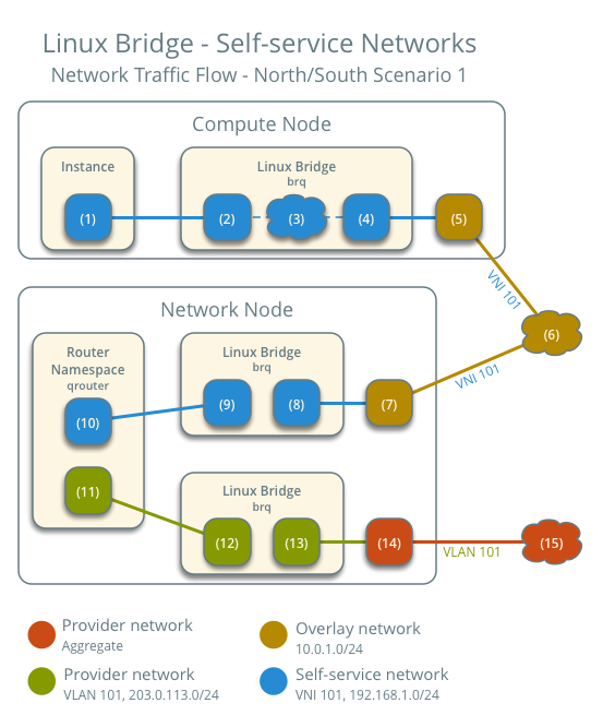
North-south scenario 1: Instance with a fixed IP address
For instances with a fixed IPv4 address, the network node performs SNAT on north-south traffic passing from self-service to external networks such as the Internet. For instances with a fixed IPv6 address, the network node performs conventional routing of traffic between self-service and external networks.
インスタンスは、コンピュートノード 1 上にあり、セルフサービスネットワーク 1 を使用します。
インスタンスが内部ネットワーク上のホストにパケットを送信します。
以下の手順は、コンピュートノード 1 で行われます。
- The instance interface (1) forwards the packet to the self-service
bridge instance port (2) via
vethpair. - Security group rules (3) on the self-service bridge handle firewalling and connection tracking for the packet.
- The self-service bridge forwards the packet to the VXLAN interface (4) which wraps the packet using VNI 101.
- The underlying physical interface (5) for the VXLAN interface forwards the packet to the network node via the overlay network (6).
以下の手順は、ネットワークノードで行われます。
- The underlying physical interface (7) for the VXLAN interface forwards the packet to the VXLAN interface (8) which unwraps the packet.
- The self-service bridge router port (9) forwards the packet to the
self-service network interface (10) in the router namespace.
- For IPv4, the router performs SNAT on the packet which changes the source IP address to the router IP address on the provider network and sends it to the gateway IP address on the provider network via the gateway interface on the provider network (11).
- For IPv6, the router sends the packet to the next-hop IP address, typically the gateway IP address on the provider network, via the provider gateway interface (11).
- The router forwards the packet to the provider bridge router port (12).
- The VLAN sub-interface port (13) on the provider bridge forwards the packet to the provider physical network interface (14).
- The provider physical network interface (14) adds VLAN tag 101 to the packet and forwards it to the Internet via physical network infrastructure (15).
注釈
Return traffic follows similar steps in reverse. However, without a floating IPv4 address, hosts on the provider or external networks cannot originate connections to instances on the self-service network.
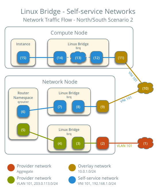
North-south scenario 2: Instance with a floating IPv4 address
For instances with a floating IPv4 address, the network node performs SNAT on north-south traffic passing from the instance to external networks such as the Internet and DNAT on north-south traffic passing from external networks to the instance. Floating IP addresses and NAT do not apply to IPv6. Thus, the network node routes IPv6 traffic in this scenario.
インスタンスは、コンピュートノード 1 上にあり、セルフサービスネットワーク 1 を使用します。
- A host on the Internet sends a packet to the instance.
以下の手順は、ネットワークノードで行われます。
- The physical network infrastructure (1) forwards the packet to the provider physical network interface (2).
- The provider physical network interface removes VLAN tag 101 and forwards the packet to the VLAN sub-interface on the provider bridge.
- The provider bridge forwards the packet to the self-service
router gateway port on the provider network (5).
- For IPv4, the router performs DNAT on the packet which changes the destination IP address to the instance IP address on the self-service network and sends it to the gateway IP address on the self-service network via the self-service interface (6).
- For IPv6, the router sends the packet to the next-hop IP address, typically the gateway IP address on the self-service network, via the self-service interface (6).
- The router forwards the packet to the self-service bridge router port (7).
- The self-service bridge forwards the packet to the VXLAN interface (8) which wraps the packet using VNI 101.
- The underlying physical interface (9) for the VXLAN interface forwards the packet to the network node via the overlay network (10).
以下の手順は、コンピュートノードで行われます。
- The underlying physical interface (11) for the VXLAN interface forwards the packet to the VXLAN interface (12) which unwraps the packet.
- Security group rules (13) on the self-service bridge handle firewalling and connection tracking for the packet.
- The self-service bridge instance port (14) forwards the packet to
the instance interface (15) via
vethpair.
注釈
Egress instance traffic flows similar to north-south scenario 1, except SNAT changes the source IP address of the packet to the floating IPv4 address rather than the router IP address on the provider network.
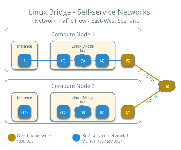
East-west scenario 1: Instances on the same network
Instances with a fixed IPv4/IPv6 or floating IPv4 address on the same network communicate directly between compute nodes containing those instances.
By default, the VXLAN protocol lacks knowledge of target location and uses multicast to discover it. After discovery, it stores the location in the local forwarding database. In large deployments, the discovery process can generate a significant amount of network that all nodes must process. To eliminate the latter and generally increase efficiency, the Networking service includes the layer-2 population mechanism driver that automatically populates the forwarding database for VXLAN interfaces. The example configuration enables this driver. For more information, see ML2 プラグイン.
- Instance 1 resides on compute node 1 and uses self-service network 1.
- Instance 2 resides on compute node 2 and uses self-service network 1.
インスタンス 1 がインスタンス 2 にパケットを送信します。
以下の手順は、コンピュートノード 1 で行われます。
- The instance 1 interface (1) forwards the packet to the
self-service bridge instance port (2) via
vethpair. - Security group rules (3) on the self-service bridge handle firewalling and connection tracking for the packet.
- The self-service bridge forwards the packet to the VXLAN interface (4) which wraps the packet using VNI 101.
- The underlying physical interface (5) for the VXLAN interface forwards the packet to compute node 2 via the overlay network (6).
以下の手順は、コンピュートノード 2 で行われます。
- The underlying physical interface (7) for the VXLAN interface forwards the packet to the VXLAN interface (8) which unwraps the packet.
- Security group rules (9) on the self-service bridge handle firewalling and connection tracking for the packet.
- The self-service bridge instance port (10) forwards the packet to
the instance 1 interface (11) via
vethpair.
注釈
戻りのトラフィックは、同様の手順の逆順で処理されます。
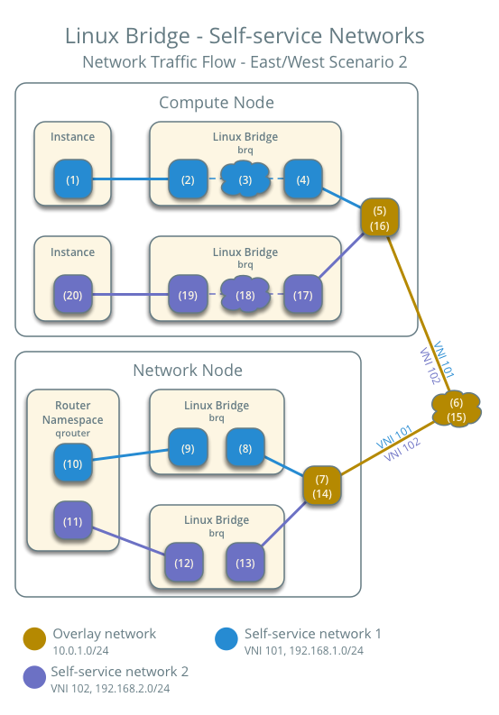
East-west scenario 2: Instances on different networks
Instances using a fixed IPv4/IPv6 address or floating IPv4 address communicate via router on the network node. The self-service networks must reside on the same router.
- Instance 1 resides on compute node 1 and uses self-service network 1.
- Instance 2 resides on compute node 1 and uses self-service network 2.
インスタンス 1 がインスタンス 2 にパケットを送信します。
注釈
Both instances reside on the same compute node to illustrate how VXLAN enables multiple overlays to use the same layer-3 network.
以下の手順は、コンピュートノードで行われます。
- The instance 1 interface (1) forwards the packet to the self-service
bridge instance port (2) via
vethpair. - Security group rules (3) on the self-service bridge handle firewalling and connection tracking for the packet.
- The self-service bridge forwards the packet to the VXLAN interface (4) which wraps the packet using VNI 101.
- The underlying physical interface (5) for the VXLAN interface forwards the packet to the network node via the overlay network (6).
以下の手順は、ネットワークノードで行われます。
- The underlying physical interface (7) for the VXLAN interface forwards the packet to the VXLAN interface (8) which unwraps the packet.
- The self-service bridge router port (9) forwards the packet to the self-service network 1 interface (10) in the router namespace.
- The router sends the packet to the next-hop IP address, typically the gateway IP address on self-service network 2, via the self-service network 2 interface (11).
- The router forwards the packet to the self-service network 2 bridge router port (12).
- The self-service network 2 bridge forwards the packet to the VXLAN interface (13) which wraps the packet using VNI 102.
- The physical network interface (14) for the VXLAN interface sends the packet to the compute node via the overlay network (15).
以下の手順は、コンピュートノードで行われます。
- The underlying physical interface (16) for the VXLAN interface sends the packet to the VXLAN interface (17) which unwraps the packet.
- Security group rules (18) on the self-service bridge handle firewalling and connection tracking for the packet.
- The self-service bridge instance port (19) forwards the packet to
the instance 2 interface (20) via
vethpair.
注釈
戻りのトラフィックは、同様の手順の逆順で処理されます。

Except where otherwise noted, this document is licensed under Creative Commons Attribution 3.0 License. See all OpenStack Legal Documents.