Linux bridge: プロバイダーネットワーク
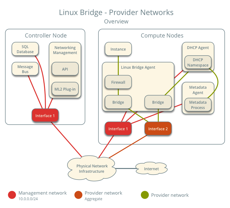
The provider networks architecture example provides layer-2 connectivity between instances and the physical network infrastructure using VLAN (802.1q) tagging. It supports one untagged (flat) network and and up to 4095 tagged (VLAN) networks. The actual quantity of VLAN networks depends on the physical network infrastructure. For more information on provider networks, see プロバイダーネットワーク.
前提
One controller node with the following components:
- Two network interfaces: management and provider.
- OpenStack Networking server service and ML2 plug-in.
Two compute nodes with the following components:
- Two network interfaces: management and provider.
- OpenStack Networking Linux bridge layer-2 agent, DHCP agent, metadata agent, and any dependencies.
注釈
Larger deployments typically deploy the DHCP and metadata agents on a subset of compute nodes to increase performance and redundancy. However, too many agents can overwhelm the message bus. Also, to further simplify any deployment, you can omit the metadata agent and use a configuration drive to provide metadata to instances.
アーキテクチャー
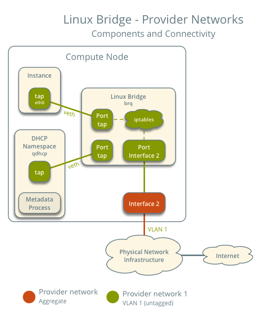
The following figure shows components and connectivity for one untagged (flat) network. In this particular case, the instance resides on the same compute node as the DHCP agent for the network. If the DHCP agent resides on another compute node, the latter only contains a DHCP namespace and Linux bridge with a port on the provider physical network interface.
The following figure describes virtual connectivity among components for two tagged (VLAN) networks. Essentially, each network uses a separate bridge that contains a port on the VLAN sub-interface on the provider physical network interface. Similar to the single untagged network case, the DHCP agent may reside on a different compute node.
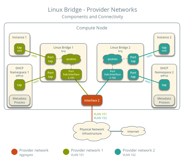
注釈
These figures omit the controller node because it does not handle instance network traffic.
設定例
Use the following example configuration as a template to deploy provider networks in your environment.
コントローラーノード
Install the Networking service components that provides the
neutron-serverservice and ML2 plug-in.neutron.confファイル:共通のオプションを設定します。
[DEFAULT]
core_plugin = ml2
auth_strategy = keystone

[database]
# ...

[keystone_authtoken]
# ...

[nova]
# ...

[agent]
# ...
See the Installation Tutorials and Guides and Configuration Reference for your OpenStack release to obtain the appropriate additional configuration for the
[DEFAULT],[database],[keystone_authtoken],[nova], and[agent]sections.Disable service plug-ins because provider networks do not require any. However, this breaks portions of the dashboard that manage the Networking service. See the Ocata Install Tutorials and Guides for more information.
[DEFAULT]
service_plugins =
Enable two DHCP agents per network so both compute nodes can provide DHCP service provider networks.
[DEFAULT]
dhcp_agents_per_network = 2
必要であれば MTU を設定します。
ml2_conf.iniファイル:ドライバーとネットワークタイプを設定します。
[ml2]
type_drivers = flat,vlan
tenant_network_types =
mechanism_drivers = linuxbridge
extension_drivers = port_security
ネットワークマッピングを設定します。
[ml2_type_flat]
flat_networks = provider

[ml2_type_vlan]
network_vlan_ranges = provider
注釈
tenant_network_typesオプションには何も値を指定しません。このアーキテクチャーでは、セルフサービスネットワークがサポートされないからです。注釈
network_vlan_rangesオプションのprovider値に VLAN ID を指定しなかった場合、任意の VLAN ID を使用できます。
データベースを展開します。
# su -s /bin/sh -c "neutron-db-manage --config-file /etc/neutron/neutron.conf \
  --config-file /etc/neutron/plugins/ml2/ml2_conf.ini upgrade head" neutron
以下のサービスを実行します。
- サーバー
コンピュートノード
Install the Networking service Linux bridge layer-2 agent.
In the
neutron.conffile, configure common options:[DEFAULT] core_plugin = ml2 auth_strategy = keystone [database] # ... [keystone_authtoken] # ... [nova] # ... [agent] # ...
See the Installation Tutorials and Guides and Configuration Reference for your OpenStack release to obtain the appropriate additional configuration for the
[DEFAULT],[database],[keystone_authtoken],[nova], and[agent]sections.linuxbridge_agent.iniファイルで Linux ブリッジエージェントを設定します。[linux_bridge] physical_interface_mappings = provider:PROVIDER_INTERFACE [vxlan] enable_vxlan = False [securitygroup] firewall_driver = iptables
PROVIDER_INTERFACEは、 プロバイダーネットワークを処理するインターフェース名で置き換えます。例えば、eth1など。dhcp_agent.iniファイルで DHCP エージェントを設定します。[DEFAULT] interface_driver = linuxbridge enable_isolated_metadata = True force_metadata = True
注釈
The
force_metadataoption forces the DHCP agent to provide a host route to the metadata service on169.254.169.254regardless of whether the subnet contains an interface on a router, thus maintaining similar and predictable metadata behavior among subnets.metadata_agent.iniファイルでメタデータエージェントを設定します。[DEFAULT] nova_metadata_ip = controller metadata_proxy_shared_secret = METADATA_SECRET
The value of
METADATA_SECRETmust match the value of the same option in the[neutron]section of thenova.conffile.以下のサービスを実行します。
- Linux ブリッジエージェント
- DHCP エージェント
- メタデータエージェント
サービスの動作検証
管理プロジェクトのクレデンシャルを読み込みます。
エージェントが存在し、動作していることを確認します。
$ openstack network agent list
+--------------------------------------+--------------------+----------+-------------------+-------+-------+---------------------------+
| ID                                   | Agent Type         | Host     | Availability Zone | Alive | State | Binary                    |
+--------------------------------------+--------------------+----------+-------------------+-------+-------+---------------------------+
| 09de6af6-c5f1-4548-8b09-18801f068c57 | Linux bridge agent | compute2 |                   | True  | UP    | neutron-linuxbridge-agent |
| 188945d1-9e70-4803-a276-df924e0788a4 | Linux bridge agent | compute1 |                   | True  | UP    | neutron-linuxbridge-agent |
| e76c440d-d5f6-4316-a674-d689630b629e | DHCP agent         | compute1 | nova              | True  | UP    | neutron-dhcp-agent        |
| e67367de-6657-11e6-86a4-931cd04404bb | DHCP agent         | compute2 | nova              | True  | UP    | neutron-dhcp-agent        |
| e8174cae-6657-11e6-89f0-534ac6d0cb5c | Metadata agent     | compute1 |                   | True  | UP    | neutron-metadata-agent    |
| ece49ec6-6657-11e6-bafb-c7560f19197d | Metadata agent     | compute2 |                   | True  | UP    | neutron-metadata-agent    |
+--------------------------------------+--------------------+----------+-------------------+-------+-------+---------------------------+
初期ネットワークの作成
The configuration supports one flat or multiple VLAN provider networks. For simplicity, the following procedure creates one flat provider network.
管理プロジェクトのクレデンシャルを読み込みます。
フラットネットワークを作成します。
$ openstack network create --share --provider-physical-network provider \
  --provider-network-type flat provider1
+---------------------------+-----------+-
| Field                     | Value     |
+---------------------------+-----------+
| admin_state_up            | UP        |
| mtu                       | 1500      |
| name                      | provider1 |
| port_security_enabled     | True      |
| provider:network_type     | flat      |
| provider:physical_network | provider  |
| provider:segmentation_id  | None      |
| router:external           | Internal  |
| shared                    | True      |
| status                    | ACTIVE    |
+---------------------------+-----------+
注釈
sharedオプションを指定すると、すべてのプロジェクトがこのネットワークを使用できるようになります。プロバイダーネットワークへのアクセスを制限する方法は ロールベースアクセス制御 (RBAC) を参照してください。注釈
To create a VLAN network instead of a flat network, change
--provider:network_type flatto--provider-network-type vlanand add--provider-segmentwith a value referencing the VLAN ID.プロバイダーネットワークのIPv4サブネットを作成します。
$ openstack subnet create --subnet-range 203.0.113.0/24 --gateway 203.0.113.1 \
  --network provider1 --allocation-pool start=203.0.113.11,end=203.0.113.250 \
  --dns-nameserver 8.8.4.4 provider1-v4
+-------------------+----------------------------+
| Field             | Value                      |
+-------------------+----------------------------+
| allocation_pools  | 203.0.113.11-203.0.113.250 |
| cidr              | 203.0.113.0/24             |
| dns_nameservers   | 8.8.4.4                    |
| enable_dhcp       | True                       |
| gateway_ip        | 203.0.113.1                |
| ip_version        | 4                          |
| name              | provider1-v4               |
+-------------------+----------------------------+
注釈
Enabling DHCP causes the Networking service to provide DHCP which can interfere with existing DHCP services on the physical network infrastructure.
プロバイダーネットワークのIPv6サブネットを作成します。
$ openstack subnet create --subnet-range fd00:203:0:113::/64 --gateway fd00:203:0:113::1 \
  --ip-version 6 --ipv6-address-mode slaac --network provider1 \
  --dns-nameserver 2001:4860:4860::8844 provider1-v6
+-------------------+------------------------------------------------------+
| Field             | Value                                                |
+-------------------+------------------------------------------------------+
| allocation_pools  | fd00:203:0:113::2-fd00:203:0:113:ffff:ffff:ffff:ffff |
| cidr              | fd00:203:0:113::/64                                  |
| dns_nameservers   | 2001:4860:4860::8844                                 |
| enable_dhcp       | True                                                 |
| gateway_ip        | fd00:203:0:113::1                                    |
| ip_version        | 6                                                    |
| ipv6_address_mode | slaac                                                |
| ipv6_ra_mode      | None                                                 |
| name              | provider1-v6                                         |
+-------------------+------------------------------------------------------+
注釈
The Networking service uses the layer-3 agent to provide router advertisement. Provider networks rely on physical network infrastructure for layer-3 services rather than the layer-3 agent. Thus, the physical network infrastructure must provide router advertisement on provider networks for proper operation of IPv6.
ネットワーク動作の検証
On each compute node, verify creation of the
qdhcpnamespace.# ip netns qdhcp-8b868082-e312-4110-8627-298109d4401c
Source a regular (non-administrative) project credentials.
Create the appropriate security group rules to allow
pingand SSH access instances using the network.$ openstack security group rule create --proto icmp default +------------------+-----------+ | Field | Value | +------------------+-----------+ | direction | ingress | | ethertype | IPv4 | | protocol | icmp | | remote_ip_prefix | 0.0.0.0/0 | +------------------+-----------+ $ openstack security group rule create --ethertype IPv6 --proto ipv6-icmp default +-----------+-----------+ | Field | Value | +-----------+-----------+ | direction | ingress | | ethertype | IPv6 | | protocol | ipv6-icmp | +-----------+-----------+ $ openstack security group rule create --proto tcp --dst-port 22 default +------------------+-----------+ | Field | Value | +------------------+-----------+ | direction | ingress | | ethertype | IPv4 | | port_range_max | 22 | | port_range_min | 22 | | protocol | tcp | | remote_ip_prefix | 0.0.0.0/0 | +------------------+-----------+ $ openstack security group rule create --ethertype IPv6 --proto tcp --dst-port 22 default +------------------+-----------+ | Field | Value | +------------------+-----------+ | direction | ingress | | ethertype | IPv6 | | port_range_max | 22 | | port_range_min | 22 | | protocol | tcp | +------------------+-----------+
Launch an instance with an interface on the provider network. For example, a CirrOS image using flavor ID 1.
$ openstack server create --flavor 1 --image cirros \
  --nic net-id=NETWORK_ID provider-instance1
Replace
NETWORK_IDwith the ID of the provider network.Determine the IPv4 and IPv6 addresses of the instance.
$ openstack server list
+--------------------------------------+--------------------+--------+------------------------------------------------------------+------------+
| ID                                   | Name               | Status | Networks                                                   | Image Name |
+--------------------------------------+--------------------+--------+------------------------------------------------------------+------------+
| 018e0ae2-b43c-4271-a78d-62653dd03285 | provider-instance1 | ACTIVE | provider1=203.0.113.13, fd00:203:0:113:f816:3eff:fe58:be4e | cirros     |
+--------------------------------------+--------------------+--------+------------------------------------------------------------+------------+
On the controller node or any host with access to the provider network,
pingthe IPv4 and IPv6 addresses of the instance.$ ping -c 4 203.0.113.13 PING 203.0.113.13 (203.0.113.13) 56(84) bytes of data. 64 bytes from 203.0.113.13: icmp_req=1 ttl=63 time=3.18 ms 64 bytes from 203.0.113.13: icmp_req=2 ttl=63 time=0.981 ms 64 bytes from 203.0.113.13: icmp_req=3 ttl=63 time=1.06 ms 64 bytes from 203.0.113.13: icmp_req=4 ttl=63 time=0.929 ms --- 203.0.113.13 ping statistics --- 4 packets transmitted, 4 received, 0% packet loss, time 3002ms rtt min/avg/max/mdev = 0.929/1.539/3.183/0.951 ms $ ping6 -c 4 fd00:203:0:113:f816:3eff:fe58:be4e PING fd00:203:0:113:f816:3eff:fe58:be4e(fd00:203:0:113:f816:3eff:fe58:be4e) 56 data bytes 64 bytes from fd00:203:0:113:f816:3eff:fe58:be4e icmp_seq=1 ttl=64 time=1.25 ms 64 bytes from fd00:203:0:113:f816:3eff:fe58:be4e icmp_seq=2 ttl=64 time=0.683 ms 64 bytes from fd00:203:0:113:f816:3eff:fe58:be4e icmp_seq=3 ttl=64 time=0.762 ms 64 bytes from fd00:203:0:113:f816:3eff:fe58:be4e icmp_seq=4 ttl=64 time=0.486 ms --- fd00:203:0:113:f816:3eff:fe58:be4e ping statistics --- 4 packets transmitted, 4 received, 0% packet loss, time 2999ms rtt min/avg/max/mdev = 0.486/0.796/1.253/0.282 ms
インスタンスにアクセスします。
Test IPv4 and IPv6 connectivity to the Internet or other external network.
ネットワークトラフィックフロー
The following sections describe the flow of network traffic in several common scenarios. North-south network traffic travels between an instance and external network such as the Internet. East-west network traffic travels between instances on the same or different networks. In all scenarios, the physical network infrastructure handles switching and routing among provider networks and external networks such as the Internet. Each case references one or more of the following components:
- プロバイダーネットワーク 1 (VLAN)
- VLAN ID 101 (タグ VLAN)
- IP アドレス範囲 203.0.113.0/24 と fd00:203:0:113::/64
- ゲートウェイ (物理ネットワーク環境経由)
- IPアドレス203.0.113.1とfd00:203:0:113:0::1
- プロバイダーネットワーク 2 (VLAN)
- VLAN ID 102 (タグ VLAN)
- IP address range 192.0.2.0/24 and fd00:192:0:2::/64
- ゲートウェイ
- IP アドレス 192.0.2.1 と fd00:192:0:2::1
- インスタンス 1
- IP アドレス 203.0.113.101 と fd00:203:0:113:0::101
- インスタンス 2
- IP アドレス 192.0.2.101 と fd00:192:0:2:0::101
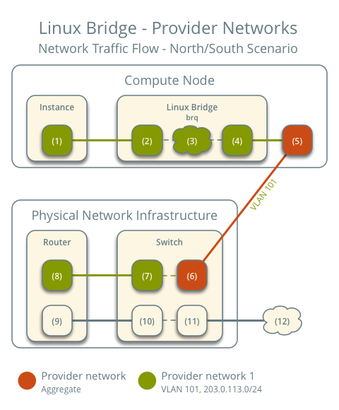
North-south scenario: Instance with a fixed IP address
- インスタンスは、コンピュートノード 1 上にあり、プロバイダーネットワーク 1 を使用します。
- インスタンスが内部ネットワーク上のホストにパケットを送信します。
以下の手順は、コンピュートノード 1 で行われます。
- The instance interface (1) forwards the packet to the provider
bridge instance port (2) via
vethpair. - Security group rules (3) on the provider bridge handle firewalling and connection tracking for the packet.
- The VLAN sub-interface port (4) on the provider bridge forwards the packet to the physical network interface (5).
- The physical network interface (5) adds VLAN tag 101 to the packet and forwards it to the physical network infrastructure switch (6).
以下の手順は、物理ネットワーク環境で行われます。
- The switch removes VLAN tag 101 from the packet and forwards it to the router (7).
- The router routes the packet from the provider network (8) to the external network (9) and forwards the packet to the switch (10).
- The switch forwards the packet to the external network (11).
- The external network (12) receives the packet.
注釈
戻りのトラフィックは、同様の手順の逆順で処理されます。
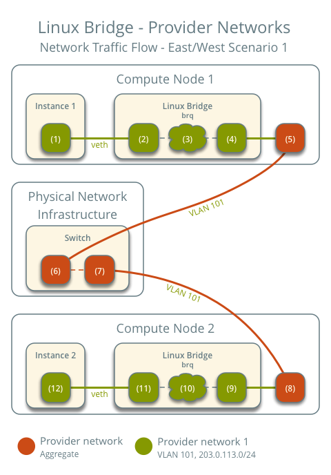
East-west scenario 1: Instances on the same network
Instances on the same network communicate directly between compute nodes containing those instances.
- インスタンス 1 はコンピュートノード 1 上にあり、プロバイダーネットワーク 1 を使用します。
- インスタンス 2 はコンピュートノード 2 上にあり、プロバイダーネットワーク 1 を使用します。
- インスタンス 1 がインスタンス 2 にパケットを送信します。
以下の手順は、コンピュートノード 1 で行われます。
- The instance 1 interface (1) forwards the packet to the provider
bridge instance port (2) via
vethpair. - Security group rules (3) on the provider bridge handle firewalling and connection tracking for the packet.
- The VLAN sub-interface port (4) on the provider bridge forwards the packet to the physical network interface (5).
- The physical network interface (5) adds VLAN tag 101 to the packet and forwards it to the physical network infrastructure switch (6).
以下の手順は、物理ネットワーク環境で行われます。
- スイッチは、コンピュートノード 1 からコンピュートノード 2 (7) へパケットを転送します
以下の手順は、コンピュートノード 2 で行われます。
- The physical network interface (8) removes VLAN tag 101 from the packet and forwards it to the VLAN sub-interface port (9) on the provider bridge.
- Security group rules (10) on the provider bridge handle firewalling and connection tracking for the packet.
- The provider bridge instance port (11) forwards the packet to
the instance 2 interface (12) via
vethpair.
注釈
戻りのトラフィックは、同様の手順の逆順で処理されます。
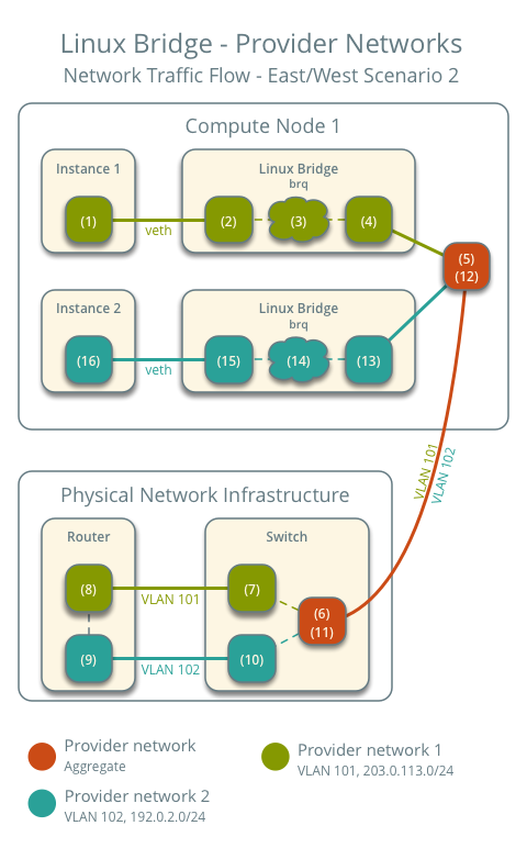
East-west scenario 2: Instances on different networks
Instances communicate via router on the physical network infrastructure.
- インスタンス 1 はコンピュートノード 1 上にあり、プロバイダーネットワーク 1 を使用します。
- インスタンス 2 はコンピュートノード 1 上にあり、プロバイダーネットワーク 2 を使用します。
- インスタンス 1 がインスタンス 2 にパケットを送信します。
注釈
Both instances reside on the same compute node to illustrate how VLAN tagging enables multiple logical layer-2 networks to use the same physical layer-2 network.
以下の手順は、コンピュートノードで行われます。
- The instance 1 interface (1) forwards the packet to the provider
bridge instance port (2) via
vethpair. - Security group rules (3) on the provider bridge handle firewalling and connection tracking for the packet.
- The VLAN sub-interface port (4) on the provider bridge forwards the packet to the physical network interface (5).
- The physical network interface (5) adds VLAN tag 101 to the packet and forwards it to the physical network infrastructure switch (6).
以下の手順は、物理ネットワーク環境で行われます。
- The switch removes VLAN tag 101 from the packet and forwards it to the router (7).
- ルーターは、パケットをプロバイダーネットワーク 1 (8) からプロバイダーネットワーク 2 (9) へルーティングします。
- ルーターは、パケットをスイッチ (10) に転送します。
- The switch adds VLAN tag 102 to the packet and forwards it to compute node 1 (11).
以下の手順は、コンピュートノードで行われます。
- The physical network interface (12) removes VLAN tag 102 from the packet and forwards it to the VLAN sub-interface port (13) on the provider bridge.
- Security group rules (14) on the provider bridge handle firewalling and connection tracking for the packet.
- The provider bridge instance port (15) forwards the packet to
the instance 2 interface (16) via
vethpair.
注釈
戻りのトラフィックは、同様の手順の逆順で処理されます。

Except where otherwise noted, this document is licensed under Creative Commons Attribution 3.0 License. See all OpenStack Legal Documents.